SDR-Receiver
1. About the App
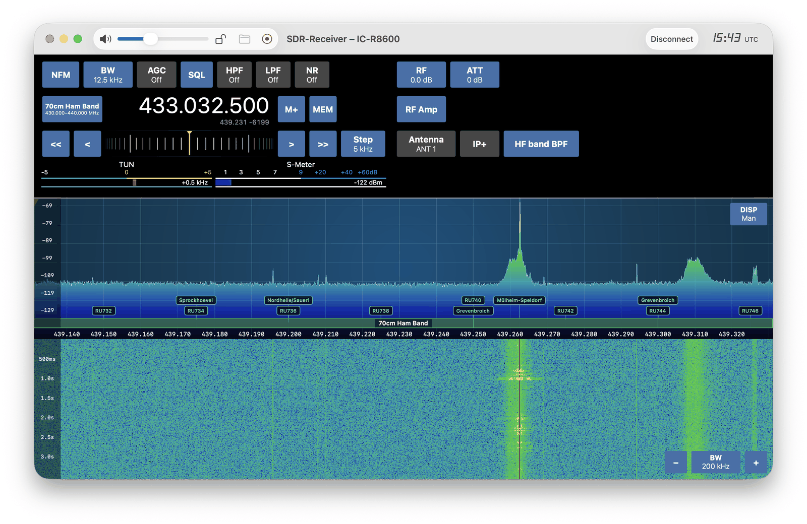
SDR-Receiver is used with a USB software-defined radio on macOS. Supported receivers range from an inexpensive RTL-SDR USB stick (about 40 USD) to a communications receiver such as the Icom IC-R8600 (about 3000 USD). After the receiver is connected, the main window shows the spectrum (FFT) and waterfall, together with the controls used to tune and listen.
The following modes can be demodulated to the speaker: WFM (broadcast FM), NFM (narrow FM), AM, SSB (USB and LSB) and CW (Morse).
The app also contains more than 25 decoders for data, speech and images. Decoded traffic can be written to a log file. Some decoders show positions on a map.
Band plans, frequency lists and memories are maintained under Tools. The included band plan is shown on the spectrum. The frequency list contains a General catalog and the EiBi shortwave list. EiBi is a published schedule of broadcast stations, including names and transmission times in UTC. The Stations at VFO window lists catalog entries for the frequency currently tuned.
The Scanner searches a frequency range, a list of memories or a frequency list for signals.
I/Q recording stores the raw samples from the receiver. During playback, the recording is used as if the receiver were still connected: the frequency can be tuned within the captured bandwidth, the demodulation mode can be changed, and decoders can be used. A separate audio recorder stores only the speaker audio. Recording can follow the signal so that silent periods are not written to the file.
1.1. Troubleshooting
Should you encounter any issues, please refer to the Common Issues section of the manual first. If no solution is listed there, use Contact Support in the app (Help menu, or SDR-Receiver ▸ Settings… then Support).
2. The manual
This manual describes how to use SDR-Receiver: connecting a receiver, the main window, decoders, tools and additional views.
The manual can be opened from inside the app (Help ▸ SDR-Receiver Help, or SDR-Receiver ▸ Settings… then Open the App Manual) or in a browser:
https://go-to.me/sdr-receiver-manual
For a printed copy, or to save a PDF, click here.
The manual is updated from time to time.
3. Requirements
SDR-Receiver requires macOS 26 or later. Older macOS versions are not supported.
A purchase on the App Store can be used on more than one Mac. Use the same Apple ID on each Mac.
SDR-Receiver works with the following USB receivers:
RTL-SDR (and variants)
Airspy
Airspy HF+
Microtelecom Perseus
Icom IC-R8600
Icom IC-7760
FUNcube Dongle Pro+
HackRF
ADALM Pluto (and variants)
The receiver must be connected to the Mac by USB.
These receivers are not interchangeable. What a radio can hear decides which decoders can be used with it: some cover shortwave and not the VHF bands, some the reverse, and only a few reach the long-wave time stations. For a comparison of every supported receiver — the range and bandwidth each one offers, and which decoders that allows — see Choosing an SDR:
4. Connecting the Receiver
The receiver must be connected to the Mac by USB. On the Icom IC-R8600, use the USB cable on the receiver’s I/Q outlet — not the CI-V or audio connection.
Click the centre of the window, or Connect at the top, to open the Receivers list. The first time this list is opened it contains only the Demo Receiver.
4.1. Adding a receiver
Click Add. Choose the receiver type.
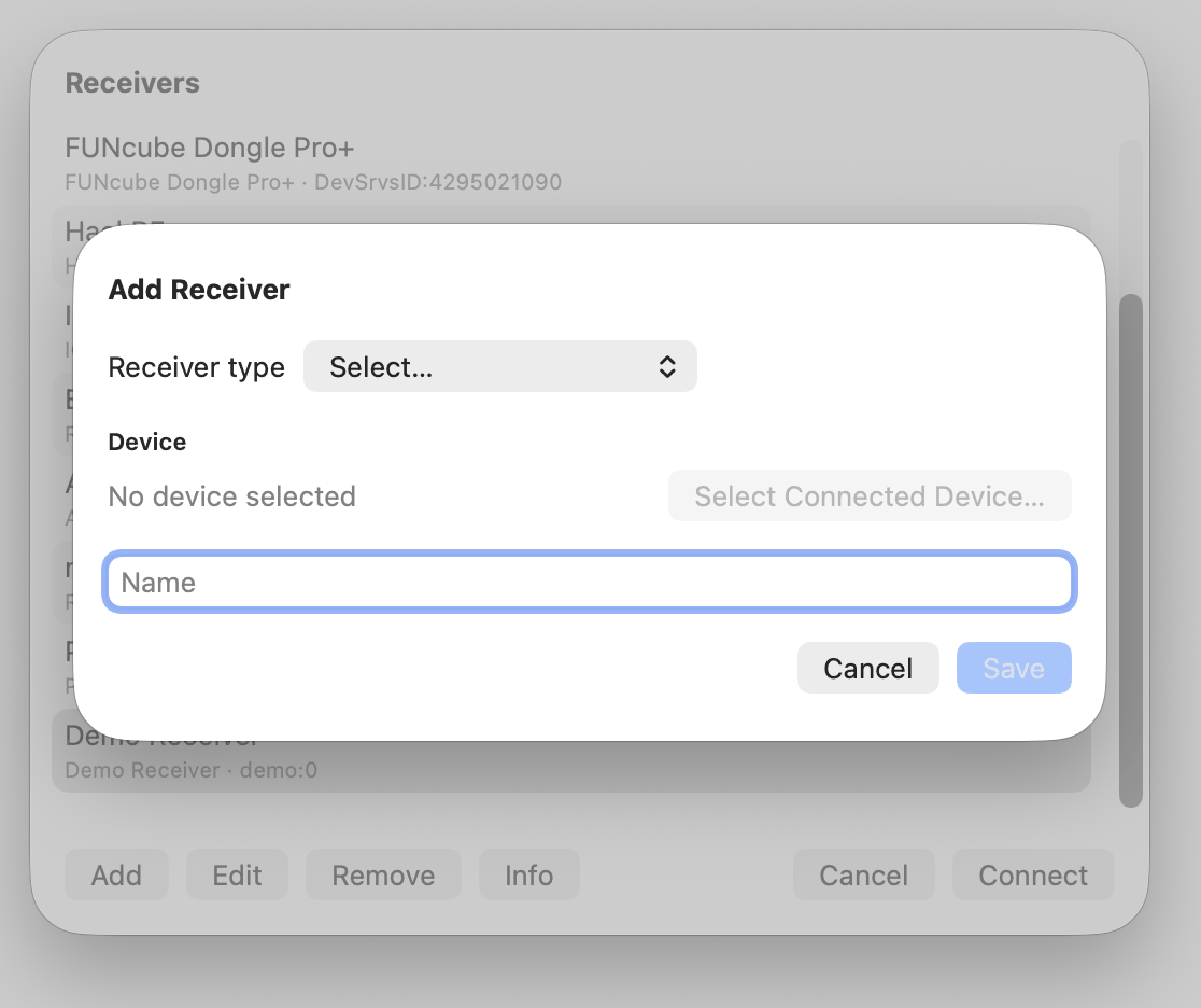
Then click Select Connected Device…. That scans for devices of the chosen type that are currently plugged in. Select the device and return to the previous screen.
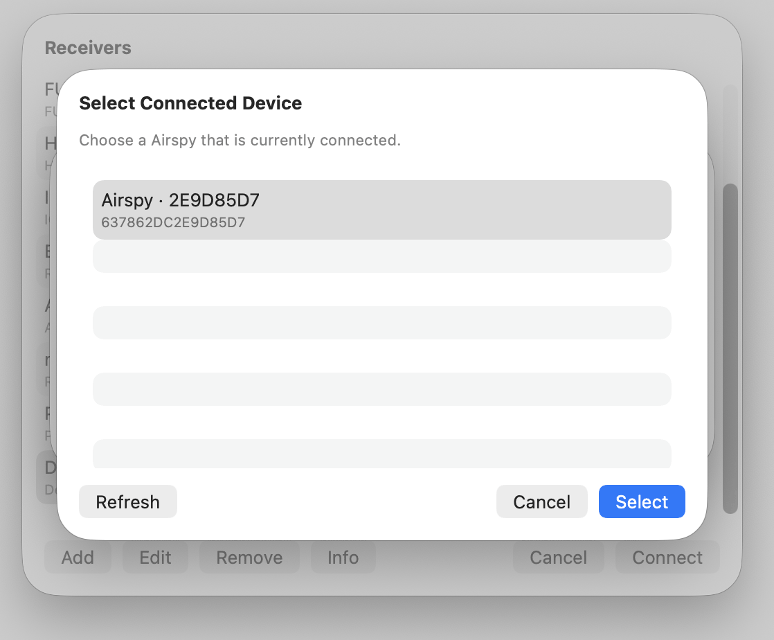
The name is filled in automatically. Change it if more than one receiver of the same type is used; otherwise leave the default. Click Save. The receiver is added to the list.
Select an entry and click Info for frequency range and other specifications of that receiver.
Click Connect to open the main window.
After a connection, the settings belonging to that device are under SDR-Receiver ▸ Receiver Settings…. Sample rate is the bandwidth the radio actually captures. Zero-IF escape is described under Frequency Tuning below. The rest, including the controls only certain receivers have, is covered in Receivers.
4.2. The main window
The black strip at the top is the VFO. Mode selects demodulation: WFM (broadcast FM), NFM (narrow FM), AM, USB, LSB or CW. BW on this strip is the demodulation filter — the width of the signal sent to the speaker and to audio-based decoders. The range depends on the mode: 50 to 250 kHz in WFM, 2.5 to 25 kHz in NFM, 3 to 12 kHz in AM, 1 to 5 kHz in USB and LSB, and 200 Hz to 2 kHz in CW. Narrowing WFM helps when stations are close together, but below about 120 kHz the RDS subcarrier is filtered out as well, and the RDS decoder stops producing text.
AGC is automatic gain control on the audio. It holds the speaker level steadier: weak signals are brought up, strong signals are held back so they do not overload. Click cycles Off, Slow, Med and Fast. Off leaves the gain fixed. Slow, Med and Fast set how quickly the gain follows the signal.
SQL is squelch. When it is on, the speaker is muted until the signal is strong enough. That keeps empty channels quiet. Click turns it on or off. Option-click sets the level: higher means a stronger signal is required before audio is heard.
HPF is a high-pass filter on the speaker. It cuts low-frequency rumble and hum. LPF is a low-pass filter on the speaker. It cuts high-frequency hiss. NR is noise reduction on the speaker. Click turns each on or off. Option-click sets the cutoff (HPF, LPF) or the amount (NR). These three affect the speaker only. They do not change what a decoder receives.
DE is FM de-emphasis. An FM transmitter lifts the high tones before sending them; de-emphasis takes that lift back out, so speech and music sound natural rather than thin and hissy. The button is present only in WFM and NFM, and each of those two modes keeps its own setting, so moving between them does not carry a broadcast value onto a narrowband channel.
Click DE to choose the time constant. 50 µs is broadcast FM in Europe and most of the world, 75 µs in the Americas, Japan and South Korea. 530 µs and 750 µs are the narrowband and land-mobile values. Off leaves the audio flat. WFM starts at 75 µs and NFM starts Off; a listener in Europe will usually want WFM set to 50 µs.
Unlike HPF, LPF and NR, de-emphasis sits inside the demodulator, so it reaches audio-based decoders as well as the speaker. Data modes need flat audio, so the button dims and reads Off while APRS is receiving. It returns to the chosen setting when that decoder stops.
Band lists sections from the enabled band plans (for example maritime, broadcast or amateur). Selecting a section tunes to the centre of that range. Band plans themselves are maintained under Tools.
Click the frequency readout to type a frequency in MHz.
M+ stores a memory at the current frequency. Memories can show markers above the frequency scale. MEM recalls a stored memory. The recall list can be searched by name, tag or frequency.
<<, <, >, >> and the tuning wheel change frequency in steps set by Step.
Two meters sit under those controls. The right meter is always the S-meter. In WFM and NFM the left meter is TUN: centre means the station is on frequency, left means tuned low, right means tuned high. In the other modes the left meter is AF Level, the audio level after demodulation.
The buttons to the right of the VFO depend on the connected receiver. Controls the device does not have are hidden. Typical controls are gain or attenuator, RF amplifier and Bias-T.
Click a gain or attenuator button to set its value. Where the receiver has only a few steps, those steps are offered as a row of choices. Where it has many — an RTL-SDR tuner has 29 of them, the IC-7760 attenuator 16 — a slider is shown instead, with the number of steps written underneath. The slider moves freely and snaps to the nearest step the receiver actually has. The value above the slider is always the one the receiver has been set to, not the position of the slider.
4.3. Spectrum and waterfall
Below the VFO is the panadapter: the spectrum (FFT) above, the waterfall below.
The yellow line is the VFO — the frequency being listened to. The blue shaded area is the demodulation filter. Its width follows BW on the VFO strip.
A band ribbon (maritime, broadcast, amateur and so on) is drawn from the enabled band plans. See Band Plan under Tools. Memory markers can appear above that ribbon. Marker size and height are set in SDR-Receiver ▸ Settings….
DISP on the spectrum sets how the display is drawn. It does not change the radio.
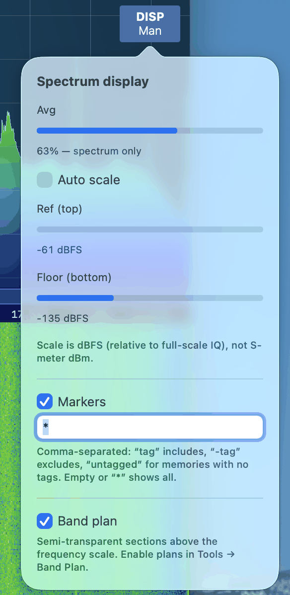
Avg smooths the spectrum trace. Auto scale sets the dB range from the signal. With Auto off, Ref (top) and Floor (bottom) are set by hand, or by dragging the dB scale on the left. The scale is dBFS relative to full-scale IQ, not the S-meter. Markers and Band plan turn the memory stems and the band ribbon on or off.
The frequency scale sits between the spectrum and the waterfall. Drag the bottom of that scale to change how much height is given to the spectrum and how much to the waterfall.
−, BW and + at the bottom of the waterfall set the displayed bandwidth (zoom). This is independent of the sample rate: the radio still captures the same width; only the view changes. The same BW popover also sets waterfall speed.
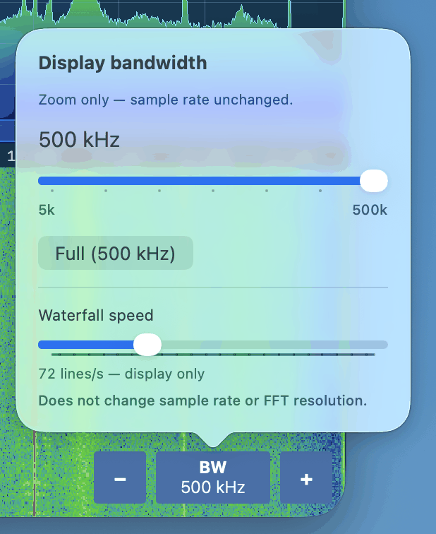
The scale on the left of the spectrum is dB. The scale on the left of the waterfall is time. Either can be dragged to change the corresponding setting.
4.4. Toolbar
At the top of the window: volume and mute, a lock, and the I/Q recording controls.
The lock stops accidental frequency changes.
4.5. I/Q recording
I/Q recording stores the samples from the receiver, not the speaker audio. Playback is used as if the receiver were still connected: the frequency can be tuned within the captured bandwidth, the demodulation mode can be changed, and decoders can be used. Audio recording is a separate tool and is described under Tools.
Files can become large. Size follows the sample rate under SDR-Receiver ▸ Receiver Settings…. As a guide, about one minute at 5 MHz produces around 1 GB. The Perseus can capture up to 2 MHz; some Airspy models more than 10 MHz.
To record, click the red record control at the top. Recording starts at once. The main window shows a red border and the elapsed time. Click the same control to stop. A file name is asked for then.
To play a recording, disconnect the receiver first. Click the file control at the top and choose the file. Playback starts immediately. Use the transport controls to pause, stop or loop.
To use a live receiver again, click Close Playback at the top right.
4.6. The Demo Receiver
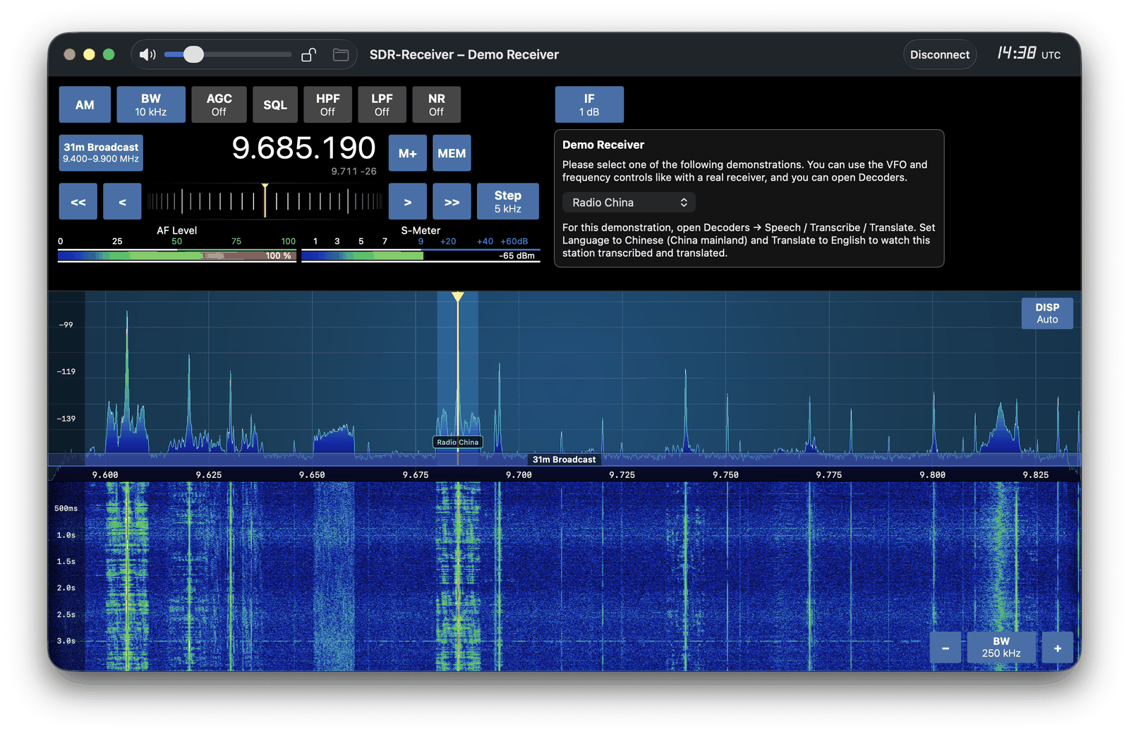
The Demo Receiver is not hardware. It plays included recordings and generated signals so the app and the decoders can be tried without a radio.
Included examples: Radio China (a foreign-language broadcast for Speech / Transcribe / Translate), DCF77, an ACARS recording, and generated RTTY, CW and ACARS.
After connecting, follow the instructions shown in the window.
4.7. Frequency tuning
The frequency can be changed in several ways:
Click the frequency readout and enter a value in MHz.
Use <<, <, >, >> next to the tuning wheel, or the wheel itself. The step size is set by Step.
Double-click a frequency on the spectrum.
Scroll the mouse wheel over the panadapter to step the VFO. Option-scroll changes the displayed bandwidth.
Drag the waterfall, or the spectrum outside the blue filter, to move the centre of the display (the LO).
Drag the blue filter or the yellow VFO line on the spectrum to move the listening frequency (the VFO).
4.8. Zero-IF escape
Some receivers produce a spike at the centre of their own spectrum (DC offset and LO leakage). If the VFO sits exactly on that centre, SSB in particular demodulates the spike as a tone in the audio.
Zero-IF escape parks the hardware centre (LO) a little above the VFO on an explicit tune, so that spike is not in the audio. The amount is set under SDR-Receiver ▸ Receiver Settings…, in the Tuning section. Set the slider to Off to place the LO on the VFO. A few decoders that need the signal at DC ignore this setting.
5. Receivers
Once a receiver is connected it is operated the same way as any other: the same VFO strip, the same panadapter, the same decoders. What differs is the hardware underneath — which socket carries the I/Q, how wide a span the device can capture, how far it tunes, and which extra controls it has.
This chapter covers the receivers that need something explained. Those not listed here need nothing beyond Connecting the Receiver. Info in the Receivers list shows the frequency range and specifications of any device.
For help choosing a receiver — what each supported radio covers, what it costs, and which decoders that allows — see Choosing an SDR:
https://sdr-receiver.com/choosing-an-sdr.html
5.1. Icom IC-R8600
Use the USB cable on the receiver’s I/Q outlet. Neither the CI-V connection nor the audio connection carries I/Q.
5.2. Icom IC-7760
The IC-7760 is a transceiver, and SDR-Receiver uses its I/Q output. Only reception is possible; the app never transmits.
Connect the Mac to the [USB] port on the rear of the RF deck. The control head has its own USB connection and it does not carry the I/Q stream — a cable there gives a working-looking setup that never produces samples.
The radio fixes the sample rate at 1.92 MHz and offers no other, so the Sample rate control in Receiver Settings has a single entry. The occupied bandwidth inside that span is about 1.66 MHz, which is why the very edges of the panadapter are empty. Receive coverage is 30 kHz to 60 MHz.
Besides the usual gain controls — RF gain, an attenuator in 3 dB steps to 45 dB, and the preamp — Receiver Settings offers IP Plus, which improves intermodulation performance, and Antenna, which selects ANT 1 to ANT 4.
I/Q Band is the control this radio has that no other does. The IC-7760 has a Main and a Sub receiver, and the I/Q port streams one at a time; this setting, in Receiver Settings, chooses which of the two feeds the app.
Main and Sub are independent receivers on independent frequencies, so each keeps its own tuning. Switch to Sub, tune to a shortwave broadcast, switch back to Main and Main is where it was left. This memory lasts as long as the receiver stays connected; it is not stored between sessions. On a fresh connection each band starts on whatever the radio itself has tuned.
5.3. RTL-SDR
An RTL-SDR’s tunable range is decided by its tuner chip, and the chips differ by more than a gigahertz. The range is read from the stick when it is opened rather than assumed, so the figure shown under Info is the one that stick can actually reach:
R820T and R828D — 24 MHz to 1766 MHz. These are the common ones.
E4000 — 64 MHz to 1700 MHz.
FC0012 — 22 MHz to 948.6 MHz. FC0013 — 22 MHz to 1100 MHz.
FC2580 — 146 to 308 MHz and 438 to 924 MHz, with a genuine gap in between.
An RTL-SDR Blog V4 is a special case. It carries its own upconverter and switches to it automatically, so it covers 500 kHz to 1766 MHz without a break and reaches the shortwave and medium-wave bands with no modification and no extra setting.
5.4. Receiver Settings
SDR-Receiver ▸ Receiver Settings… holds the settings that belong to the connected device. The window is available while a receiver is connected and is arranged in three groups.
Receiver names the connected device and sets the sample rate — the bandwidth the radio actually captures. It sets how much of the band the panadapter can show at once, and it sets how fast an I/Q recording grows. Some receivers offer a list of rates, others only one.
Tuning holds Zero-IF escape, described under Zero-IF escape.
Device setup holds the controls only certain receivers have. A control that the connected device does not have is not shown at all, so this group is empty for most receivers. Direct Sampling appears for an RTL-SDR, and I/Q Band, IP Plus and Antenna for an IC-7760.
5.5. Direct Sampling
Direct Sampling is an RTL-SDR setting. It bypasses the tuner and feeds the antenna straight to the converter chip, which is how an RTL-SDR can be made to hear shortwave at all.
What it reaches is 0 to 14.4 MHz — long wave, medium wave, the lower shortwave broadcast bands, and the amateur bands up to and including 20 m (14.000 to 14.350 MHz). Nothing above that: 17 m, 15 m, 12 m and 10 m are out of reach, and 14.4 to 24 MHz is a gap that neither direct sampling nor the ordinary tuner covers.
Most sticks need a hardware modification before this works — a wire soldered to one of the two converter inputs. An RTL-SDR Blog V3 has that circuit built in and needs no work. On an unmodified stick the setting produces only noise and images.
The choice is Off, I branch or Q branch, because the modification can be wired to either input and a stick wired for one hears nothing on the other. Q is what the standard modification and the Blog V3 both use, so try Q first. A wrong branch looks exactly like a dead receiver rather than like a wrong setting.
While direct sampling is on the tuner is powered down. There is no tuner gain to set, so that control disappears from the VFO strip until the setting is turned off again. Bias-T is unaffected; it sits on the antenna line rather than in the tuner.
The setting is not offered on an RTL-SDR Blog V4. A V4 already reaches those frequencies through its own upconverter, and switching the tuner off would take the upconverter with it.
1. Decoders
Decoders are opened from the Decoders menu. Each decoder has its own window. They copy data, speech or images from the signal: pagers, aircraft and ship traffic, packet radio, weather fax, amateur digital modes, time signals, live transcription, and others. Some also show positions on a map.
RX starts and stops decoding. Click it to turn the decoder on. While RX is on, some decoders also set the demodulation mode and bandwidth required for that signal. Closing the decoder window turns RX off and stops logging. Minimising the window leaves the decoder running.
The sections below apply to most decoder windows. Later sections cover each decoder.
1.1. Frequency selection
Where a list of known frequencies exists, the decoder offers a frequency control like this:
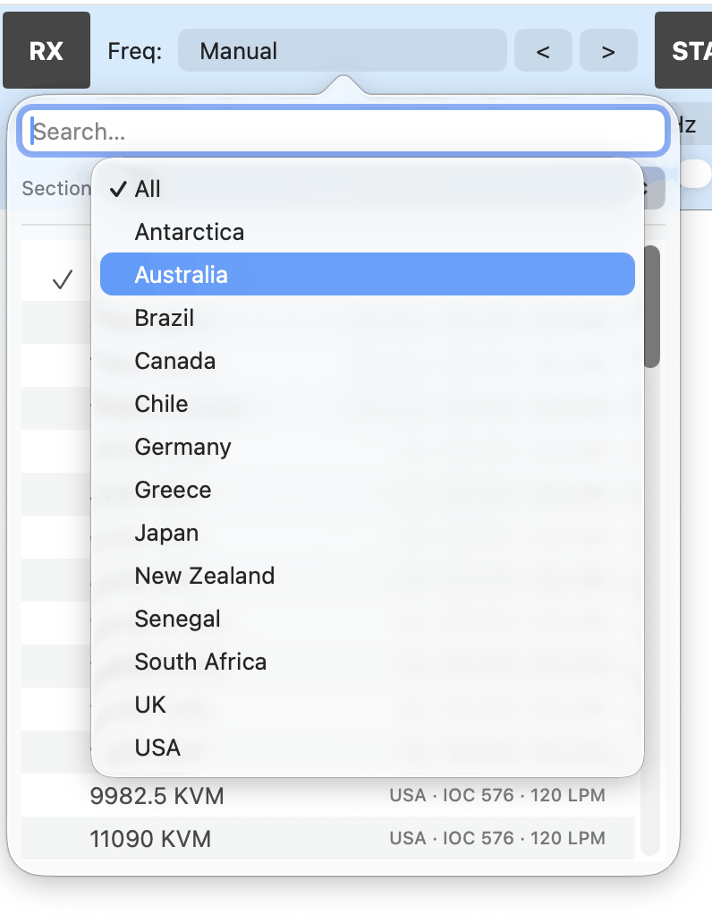
Type in the field to search. Every matching entry is listed. A section can also be chosen first, so only entries in that section are shown.
< and > to the right of the field step to the previous or next entry.
Selecting an entry tunes the receiver. Mode, bandwidth or other settings may also be set when that frequency needs them.
Manual is selected when the current frequency is not in the list, or when a frequency outside the list is used on purpose.
1.2. Filter
Many decoder windows, and some Tools windows, have a Filter field. It hides rows in the table. It does not change decoding, and it does not change what is written to a log.
Leave the field empty to show every row.
Terms can be combined with a comma. A row is kept if it matches any of the include terms. A term starting with - always hides a matching row.
Examples:
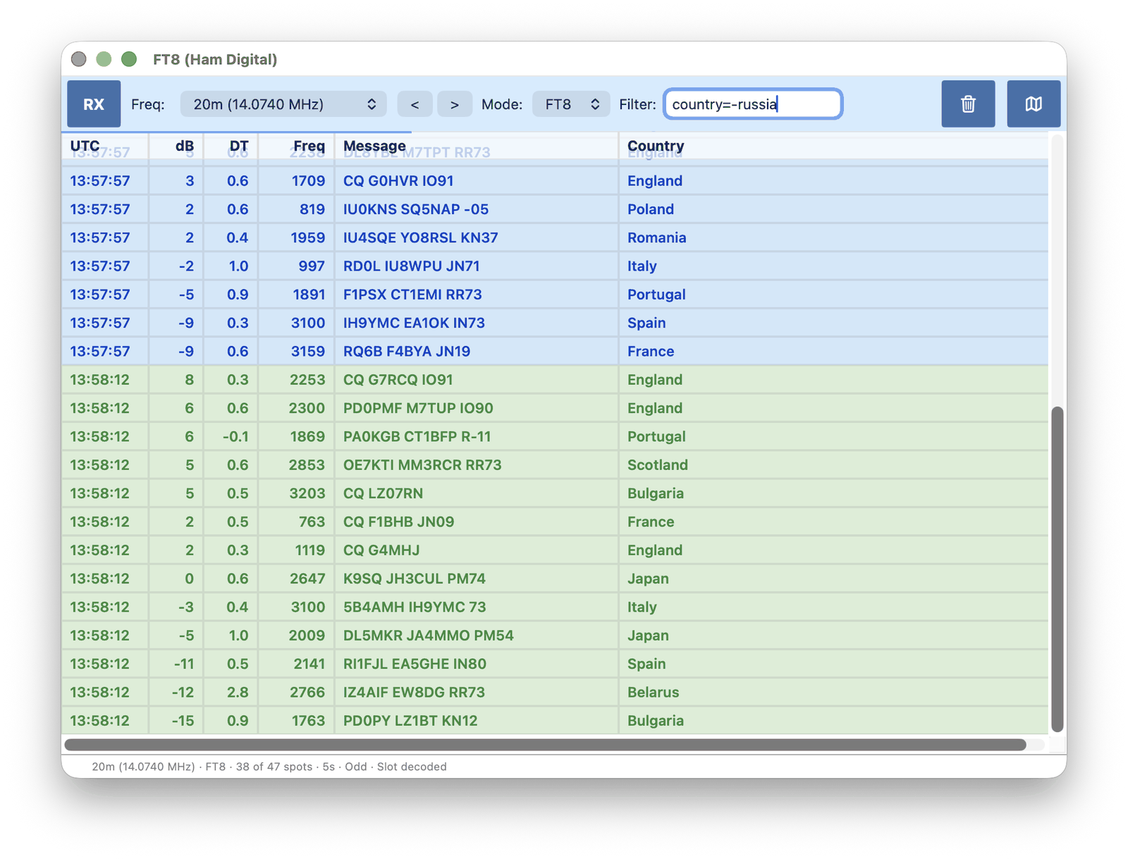
berlin— keep rows where any column contains that textberlin,hamburg— keep rows that contain either-test— hide rows that contain that textCall=K1JT— keep rows where the Call column contains that valueCountry=-russia— hide rows where the Country column contains that valuedB>-10— keep rows where the dB column is greater than −10
Column names match the table headers (not case-sensitive). = is a contains match on that column. >, >=, < and <= compare that column; the comparison is numeric when both sides are numbers.
1.3. Logging
Many decoders can write received data to a file. Click LOG, choose a file name, and logging starts. Click LOG again to stop.
The file is .csv when the window is a table of fields, and .log when the window is a text stream. Only traffic received after logging is started is written. The Filter field is ignored: the file contains everything, not only the rows on screen.
Logging also stops when RX is turned off or the decoder window is closed.
2. FSK / NAVTEX / RTTY
FSK (Frequency Shift Keying) sends text by switching between two tones. The tones are Mark and Space. Shift is the frequency difference between them. Baud is the symbol rate.
The same window covers several services that all use two-tone FSK:
Ham RTTY — amateur radio teletype, commonly 45.45 baud and 170 Hz shift
Weather RTTY — meteorological text broadcasts (for example DDH47)
NAVTEX / SITOR-B — maritime safety text on MF, with error correction
DSC — Digital Selective Calling on marine radio (alerting and calling, not a conversation)
EFR Teleswitch — long-wave utility signalling used for tariff and load switching
Frame is the character layout (start and stop bits, or a continuous code such as 4/7 for NAVTEX). Enc is the alphabet: ITA2 (Baudot) for classic RTTY, CCIR476 for NAVTEX, ASCII, DSC or Selcall. UOS (Unshift On Space) is for ITA2: after a space, the decoder returns to letters. Inv swaps Mark and Space if the station is sent inverted.
This decoder uses the IQ stream. Demodulation mode does not have to be set for decoding itself. A catalog frequency may still set USB so the signal can be heard.
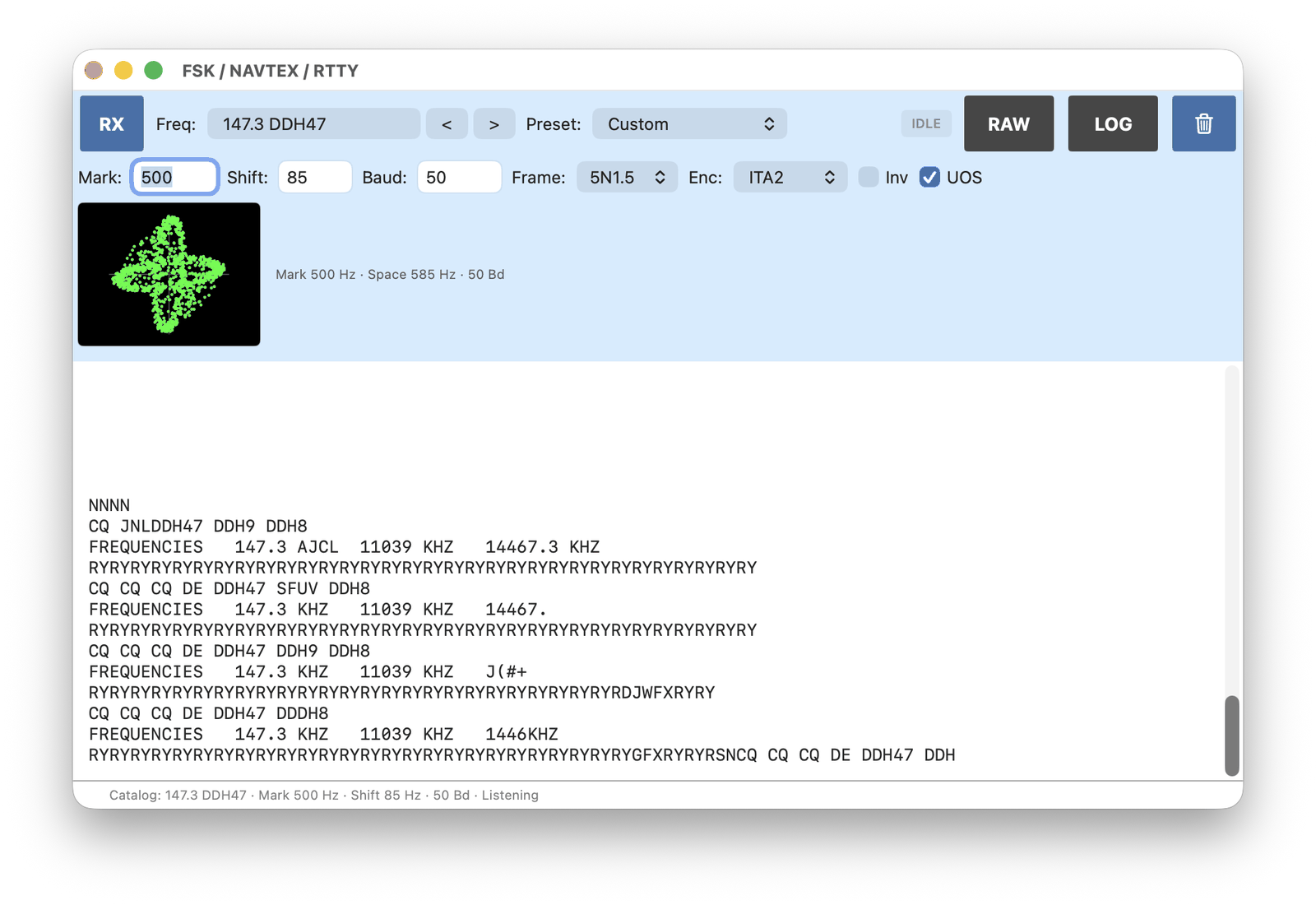
Use Freq to pick a catalog frequency, or tune manually. Preset fills Mark, Shift, Baud, Frame and Enc for a known service (Weather DDH47, Weather 50/450, Ham RTTY, NAVTEX / SITOR-B, DSC, EFR Teleswitch). The same values can be set by hand; that selects Custom.
Tuning is two steps:
Zoom the waterfall until the two FSK lines are visible. Move the frequency so the M and S markers sit on those lines.
Use the ellipse display and fine-tune until two ellipses stand at 90 degrees to each other.
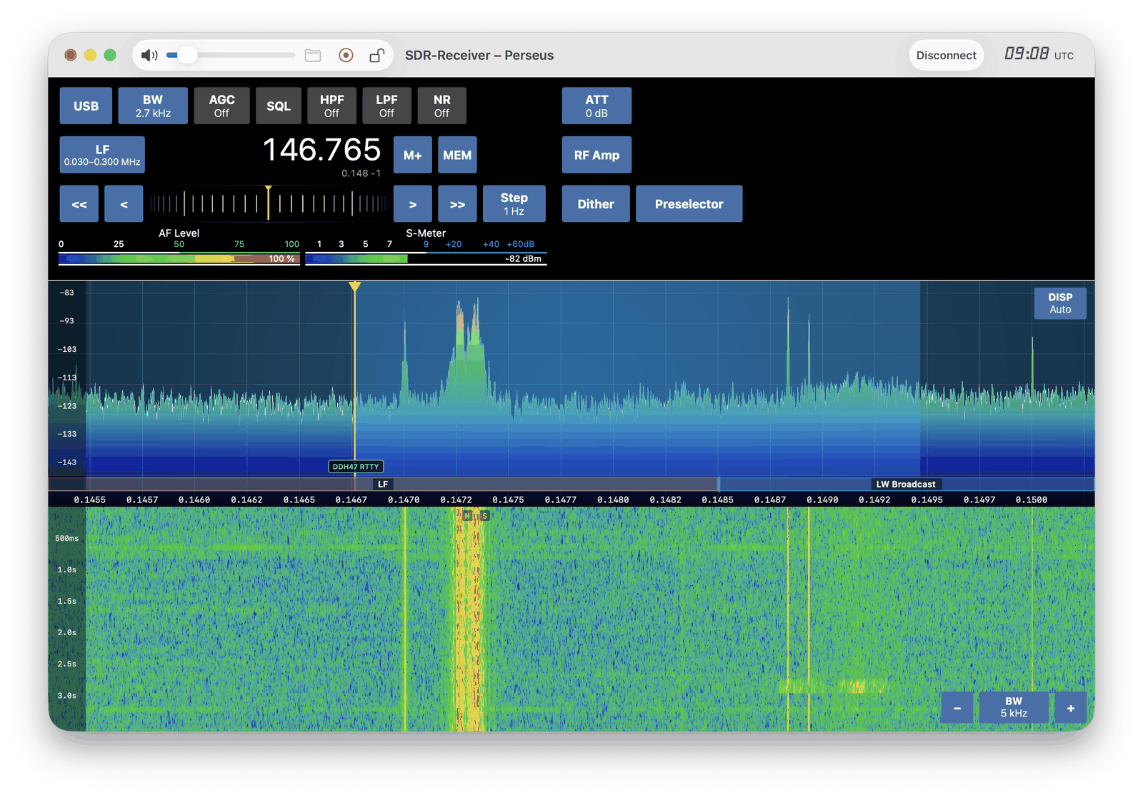
RAW shows hexadecimal instead of decoded text. LOG writes received text to a file.
3. CW (Morse Code)
CW (Morse code) is still used in amateur radio, some commercial and utility services, and by stations that send Morse rather than voice.
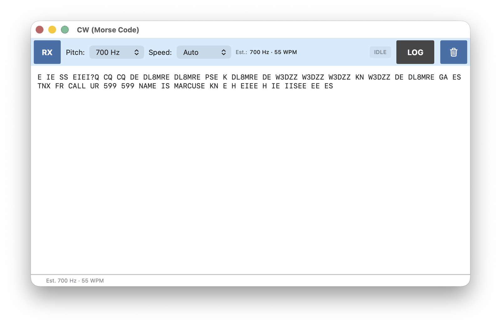
This decoder listens to the CW audio. RX sets the demodulation mode to CW. Use a narrow bandwidth (about 1 kHz). Pitch is the tone in the speaker and the tone the decoder looks for (default 700 Hz). Speed can be a fixed WPM value or Auto.
Tune to a Morse signal. Zoom the waterfall and place the signal on the small CW marker. The decoded text is shown in the window.
False characters cannot be avoided on CW. Noise and other signals are often decoded as Morse, so some garbage in the text is normal.
LOG writes decoded text to a file.
4. HF Fax / Weather FAX
HF Fax (weather facsimile) is used to send still images over shortwave, mainly weather charts from meteorological stations. The image is sent as a slow FM tone on USB.
RX sets USB and a 3 kHz bandwidth. Use Freq to pick a catalog frequency, or tune manually. A catalog entry also sets IOC, LPM, Dev and Invert for that station.
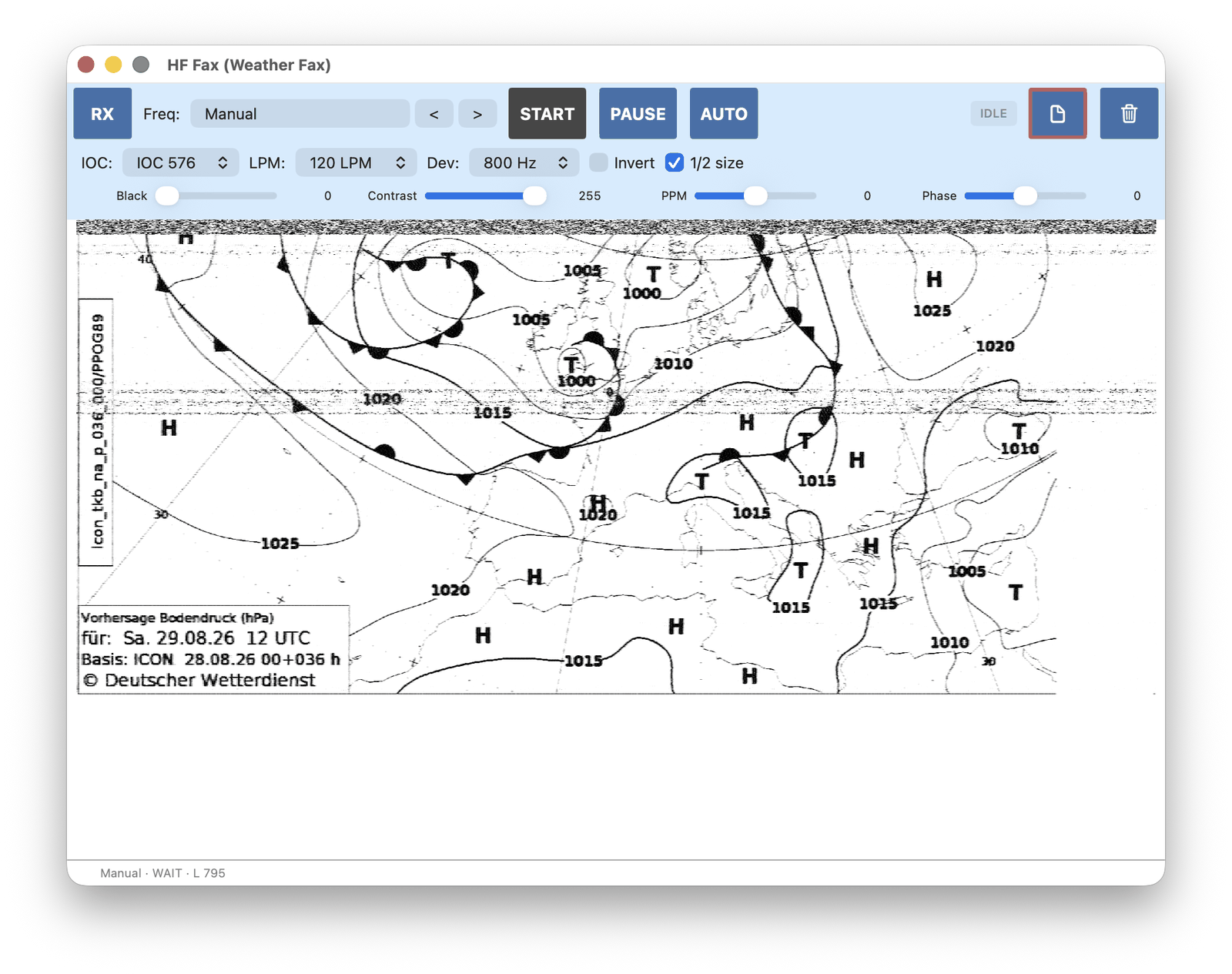
AUTO waits for the start tone of the next image. Use START if the transmission is already in progress and the start tone has been missed.
PPM corrects clock skew (a slanted image). Phase moves the image left or right.
File saves the current image, turns on Auto Save (every completed image is written to a folder), or loads a saved image so PPM and Phase can be adjusted again. A red border on the File button means Auto Save is on.
5. POCSAG (Pager)
POCSAG is the protocol used by numeric and alphanumeric pagers. SMS largely replaced it for the public, but commercial paging still exists in some countries, and amateur operators run converted pagers on ham frequencies.
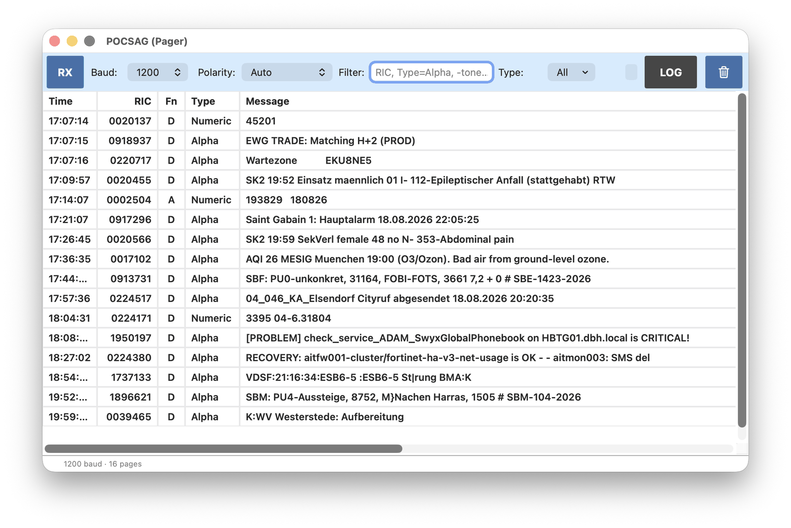
RX sets NFM and starts decoding on the current frequency. Tune to a pager channel first. Baud is 512, 1200 or 2400; 1200 is the usual rate. Polarity can be left on Auto unless the text is inverted garbage.
The table lists time, RIC (the pager address), function bits, type (tone, numeric or alpha) and the message. Type can hide kinds that are not wanted. Filter uses the same grammar as other decoder tables.
Encrypted pages are not decoded.
6. SSTV (Slow Scan TV)
SSTV sends still pictures over a voice channel. It is used mainly by amateur radio: colour images on HF (usually USB) and on VHF (usually NFM). The International Space Station (ISS) also sends SSTV on 145.800 MHz from time to time. A pass is often strong enough for an inexpensive RTL-SDR and a simple antenna.
Use Freq to pick a catalog frequency, or tune manually. Catalog entries may set the VFO and the demodulation mode. SSTV can be USB or NFM, so the mode on the main window must match the station.
RX only starts listening to the audio. Decoding starts with Start. Leave Mode on Auto VIS so the decoder reads the header and selects the picture mode. If the header has already passed, choose the mode by hand and press Start to copy the rest of the transmission.
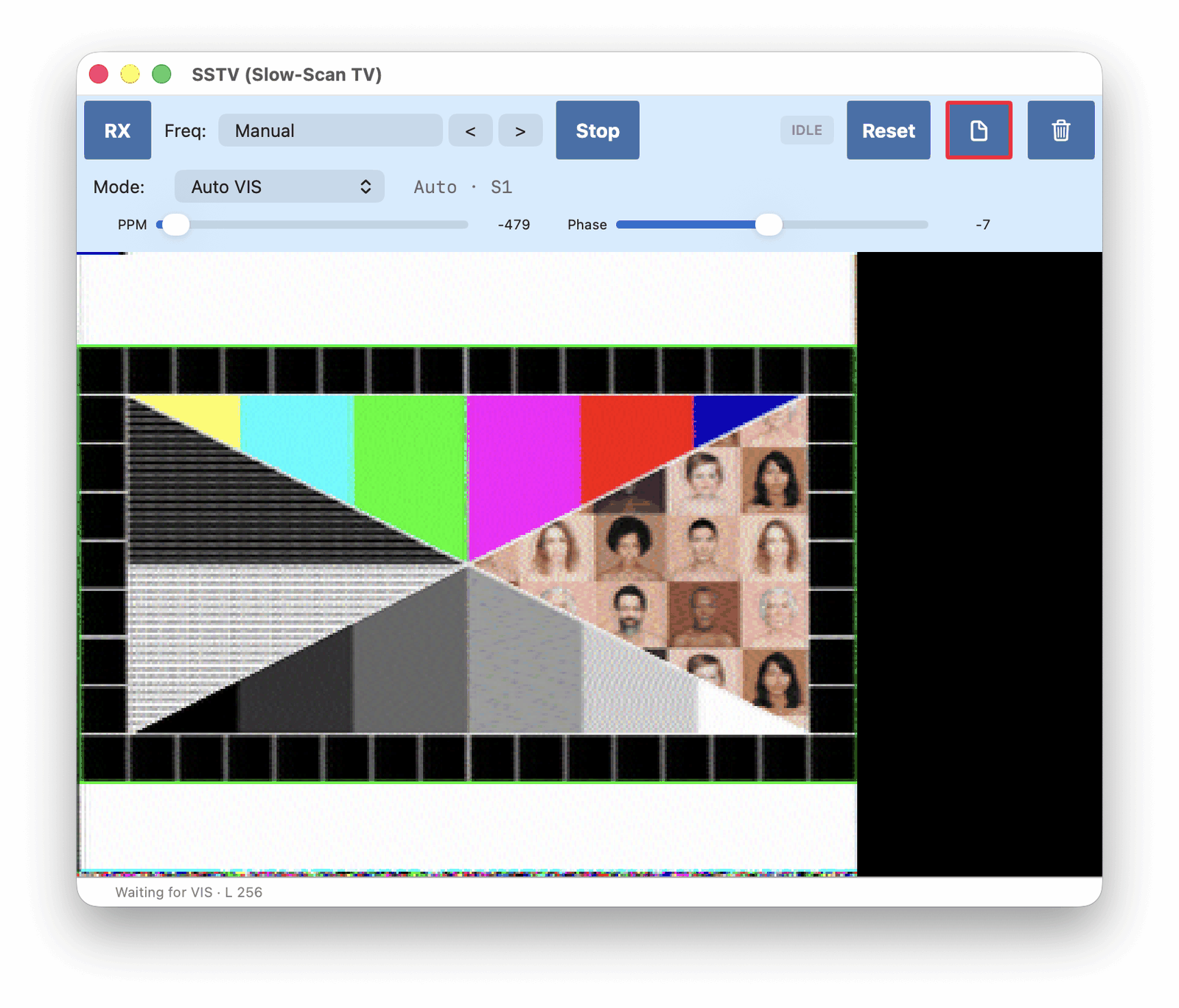
PPM corrects clock skew (a slanted image). Phase moves the image left or right. Both are available after a complete picture, or after a saved image is loaded.
File saves the current image, turns on Auto Save (every completed image is written to a folder), or loads a saved image so PPM and Phase can be adjusted again. A red border on the File button means Auto Save is on.
7. ADS-B (Air Traffic)
ADS-B is how aircraft broadcast their own identity, position, altitude and speed. Air traffic control and other aircraft use it. The transmissions are on a fixed frequency of 1090 MHz.
RX takes the receiver over: it tunes to 1090 MHz and switches to RAW. Turning RX off restores the previous frequency and mode.
The table lists aircraft and is updated as new reports arrive.
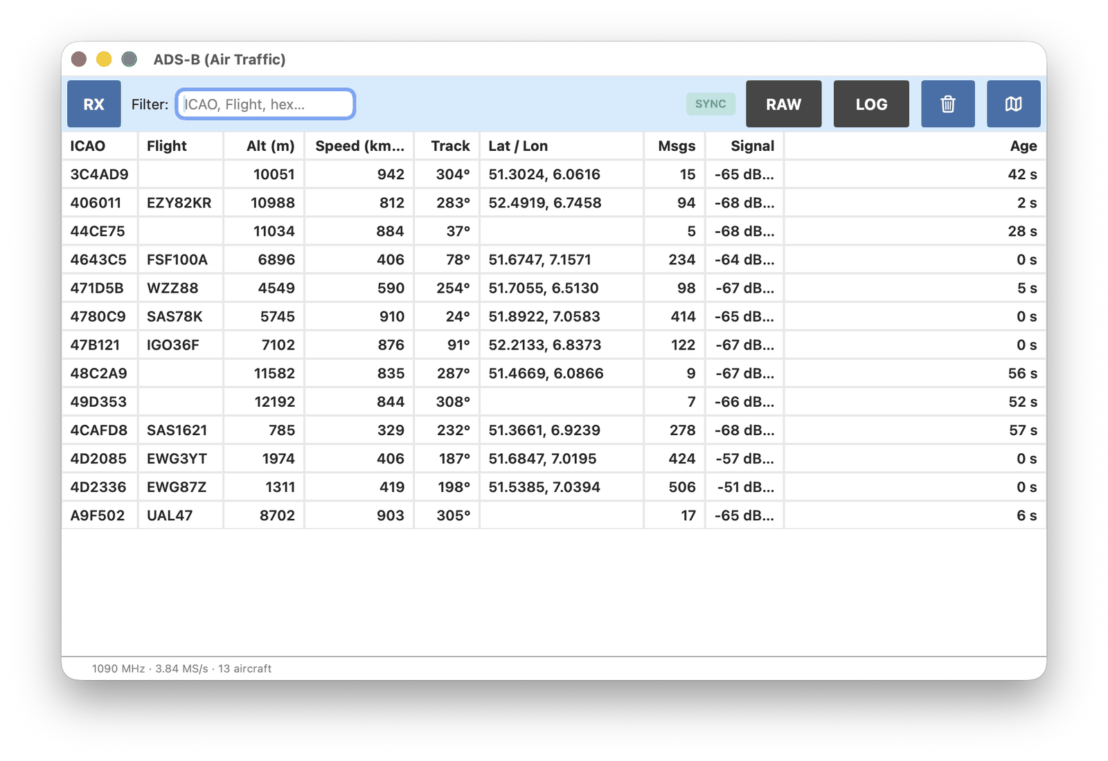
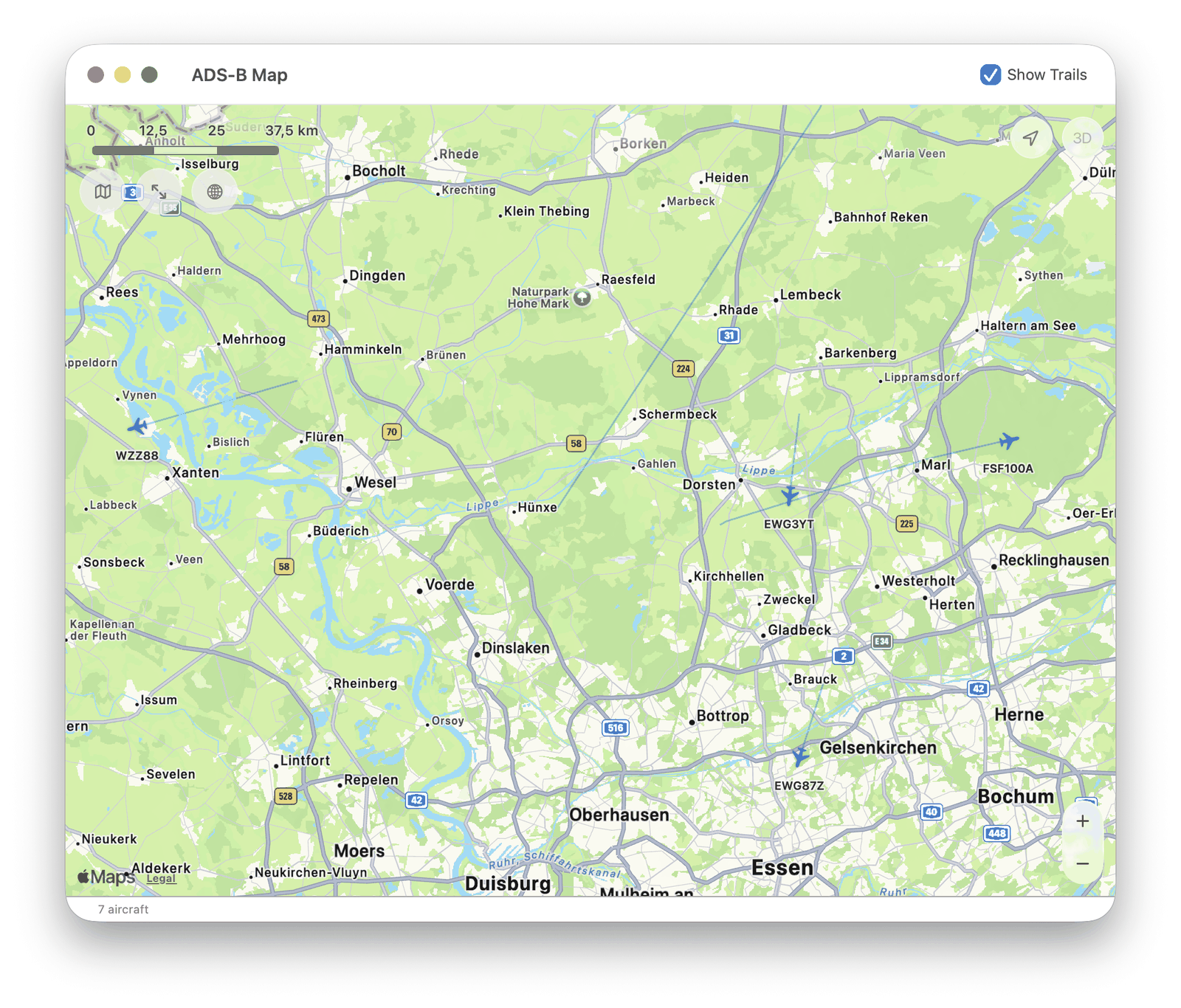
RAW shows the incoming frames instead of the aircraft list. Map shows aircraft positions and tracks.
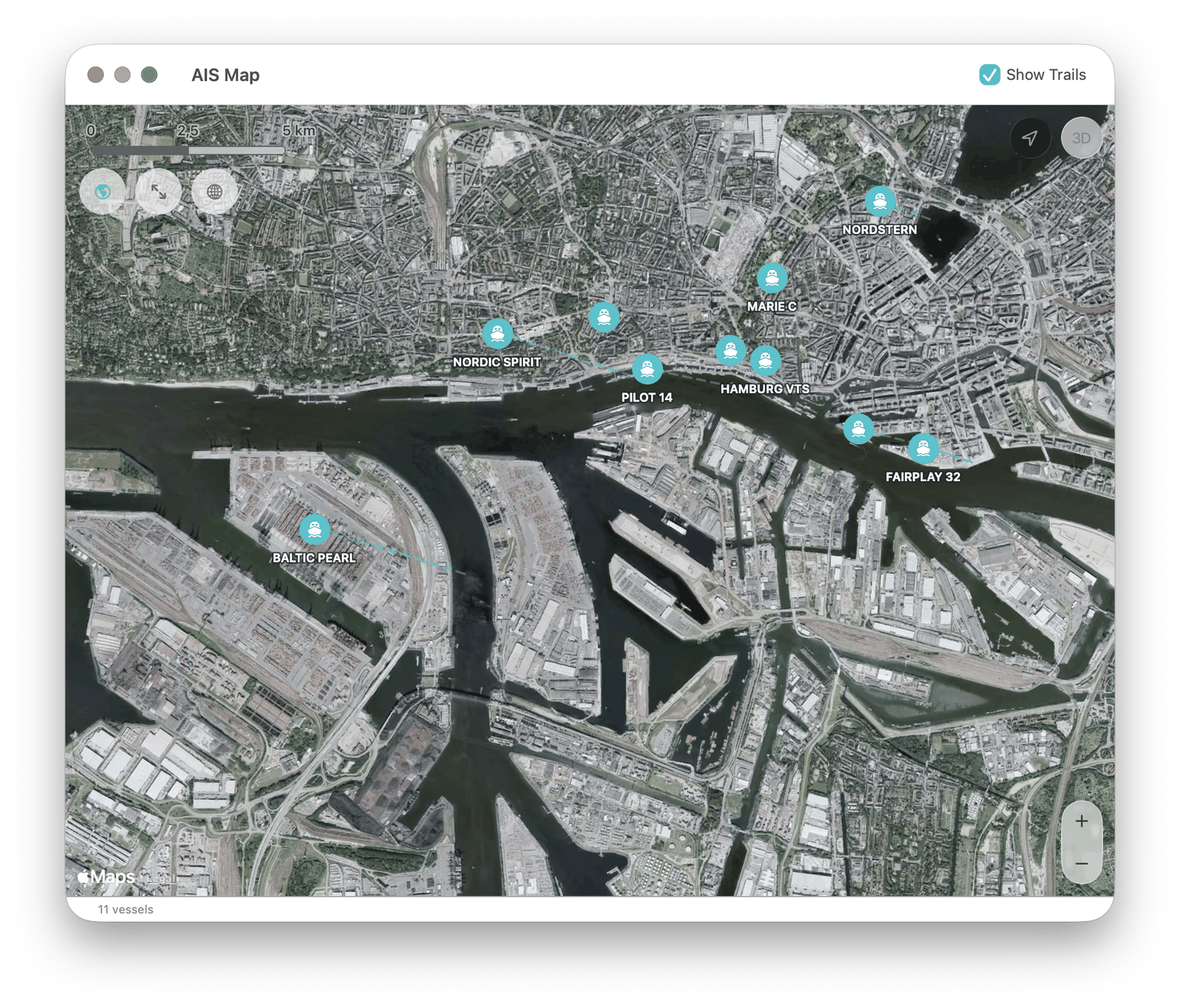
8. AIS (Ship Traffic)
AIS is how ships broadcast their identity, position, course and speed. Other vessels and shore stations use it to see traffic. The two worldwide channels are A (161.975 MHz) and B (162.025 MHz).
Vessels alternate between the two channels, so watching only one loses roughly half the traffic. A+B receives both at once and is the default. It tunes 162.000 MHz, the midpoint between the channels: nothing transmits there, so the frequency readout sits on an empty spot and the panadapter shows a signal to each side of the cursor. That is what a working A+B setup looks like.
A+B needs enough captured bandwidth to hold both channels. If the sample rate under SDR-Receiver ▸ Receiver Settings… is set too low for that, the option is not offered and only the single channels are listed.
Select a channel, then RX. RX sets NFM. Manual keeps the current VFO if a different AIS frequency is used.
The table lists vessels and is updated as reports arrive. On A+B the status line under the table counts each channel separately, as A 41 · B 38. Roughly balanced counts are normal. A badly lopsided pair points at interference or an antenna problem on one channel rather than at the decoder.
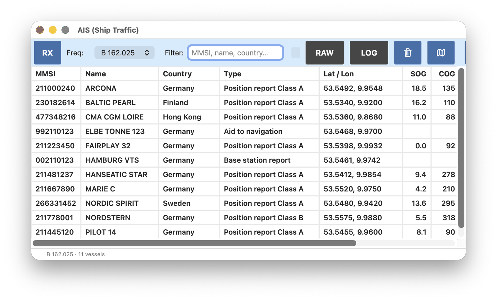
RAW shows the incoming messages instead of the vessel list. Map shows ship positions and tracks.
9. APRS (Packet Radio)
APRS is amateur packet radio used to send positions, weather reports and short messages. Stations, cars, balloons and some satellites (including the ISS) take part.
Above 30 MHz the usual mode is 1200 baud NFM. Below 30 MHz it is 300 baud SSB. Set Baud to match.
Use Freq to pick a catalog channel, or tune manually. RX starts decoding. Packets appear in the list. Click a row for the decoded detail.
APRS needs flat audio, so FM de-emphasis is turned off automatically while RX is on. The DE button on the main window dims and reads Off for as long as that lasts, and returns to its own setting when RX is turned off.
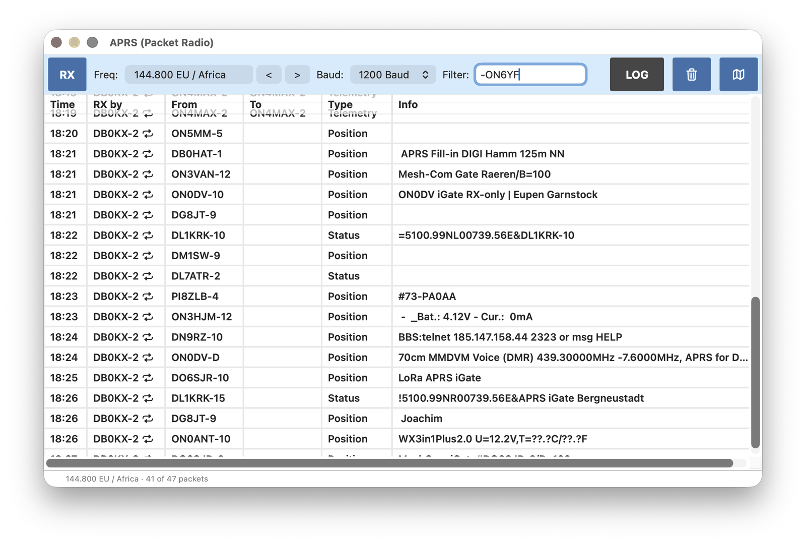
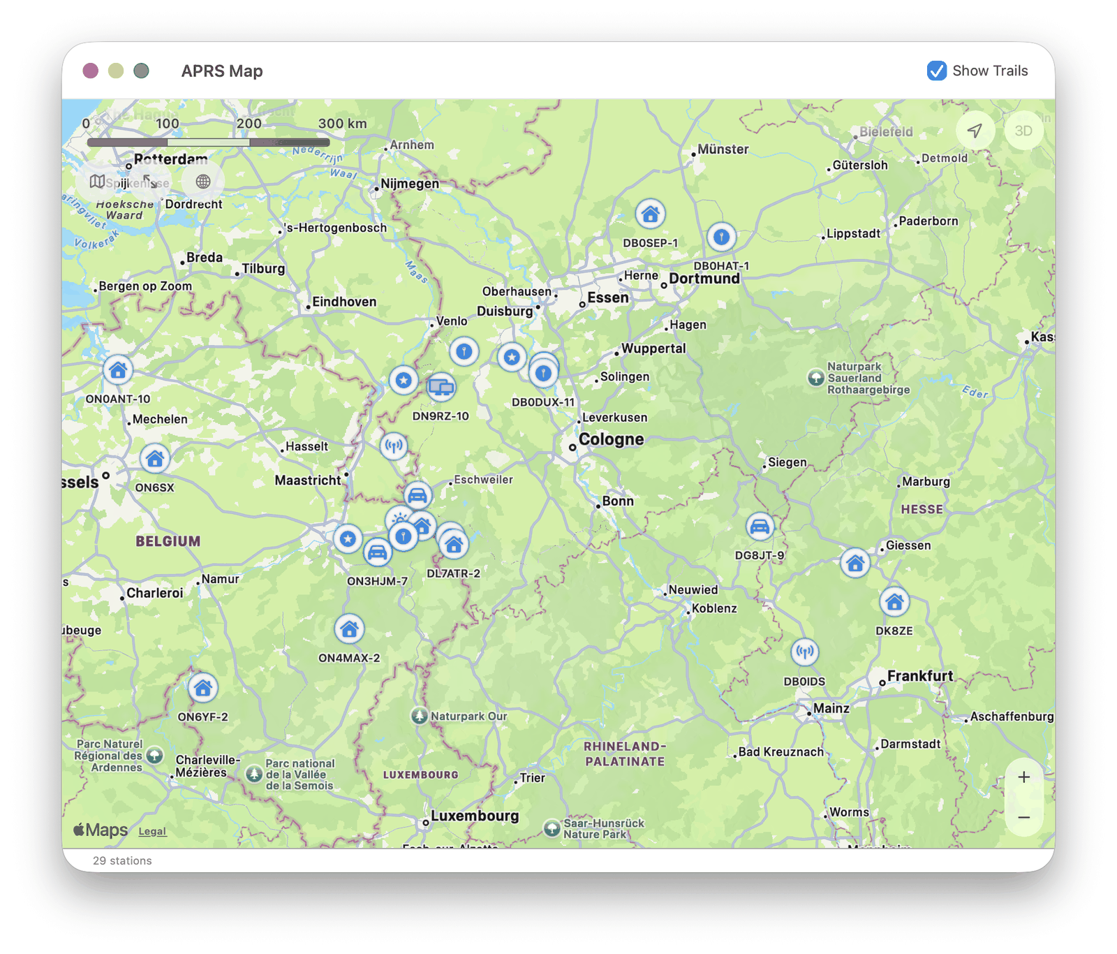
Map shows position reports.
10. ACARS (Aircraft Messages)
ACARS is a VHF data link used by aircraft to send short operational messages to the ground: departure, position, weather requests, and similar traffic. The usual channels sit around 131 MHz and depend on the region.
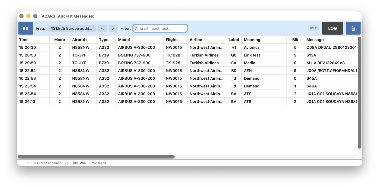
Use Freq to pick a channel for the current area, then RX. RX sets AM. Messages appear in the table.
An included aviation database fills in airline name, aircraft type and model where the registration is known. That database is updated from time to time with the app.
The 136.900 and 136.975 MHz entries are VDL2, not this decoder.
11. ALE (Automatic Linking)
ALE (Automatic Link Establishment) is used on HF so radios can find each other without an operator watching one frequency. Stations send short sounding calls, then set up a link and may send a text message. It is used by government, military and some amateur nets.
Use Freq to pick a catalog channel, then RX. RX sets USB or LSB and a 3 kHz bandwidth, as required by that entry. Manual keeps the current VFO.
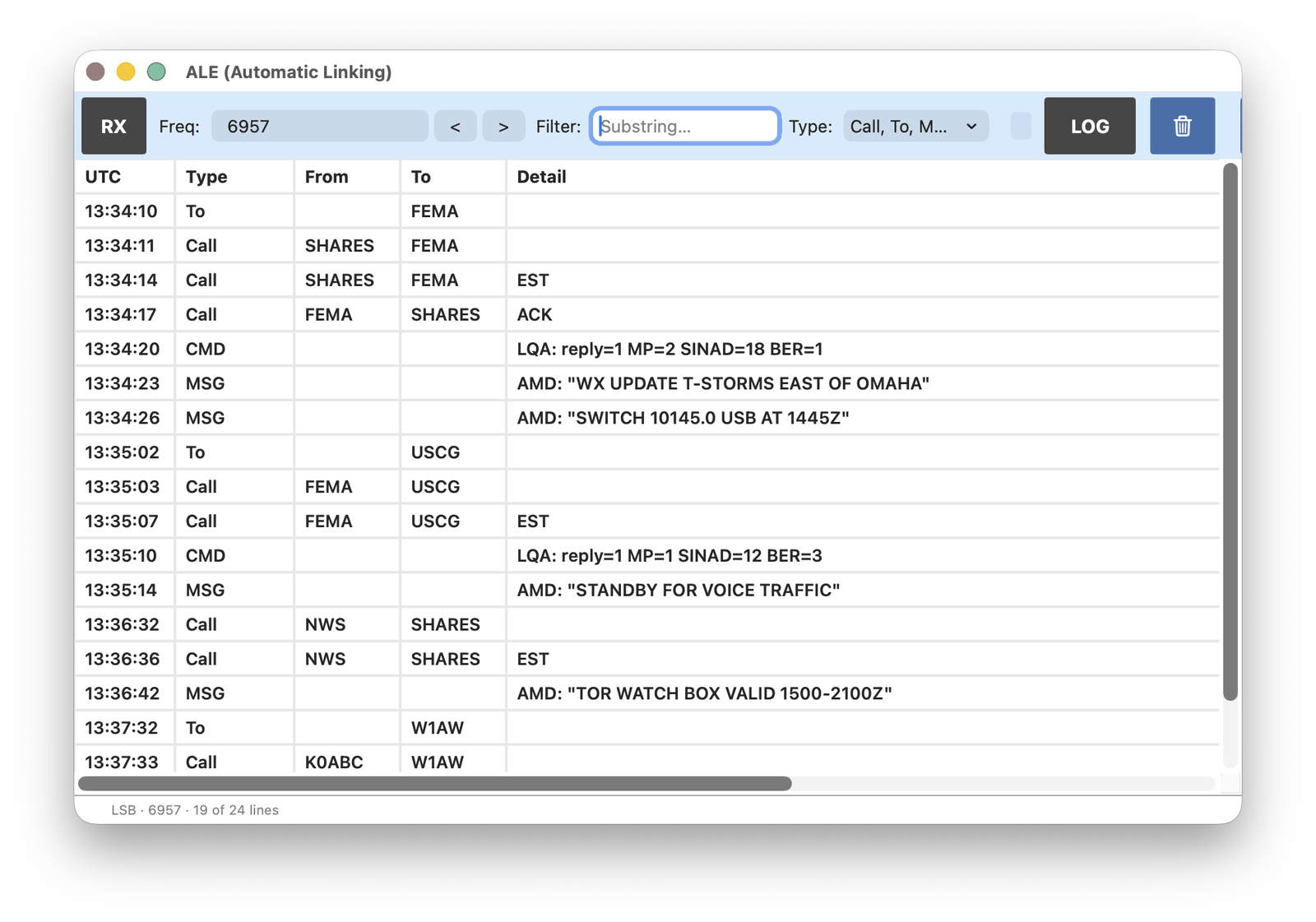
Decoded traffic is listed with time, type, from, to and the message. Type chooses what is shown (sounding, call, to, message, command). Sounding is off by default because those bursts are frequent and usually not the traffic of interest.
12. RDS (FM Radio Text)
RDS is the data sent by many broadcast FM stations together with the audio: station name, programme type, and RadioText (the scrolling line with the song title or a station message).
Tune to an FM station in WFM, then RX. The decoder does not change the frequency or the mode. The station panel shows the current name and related fields; the list below it is RadioText as it arrives.
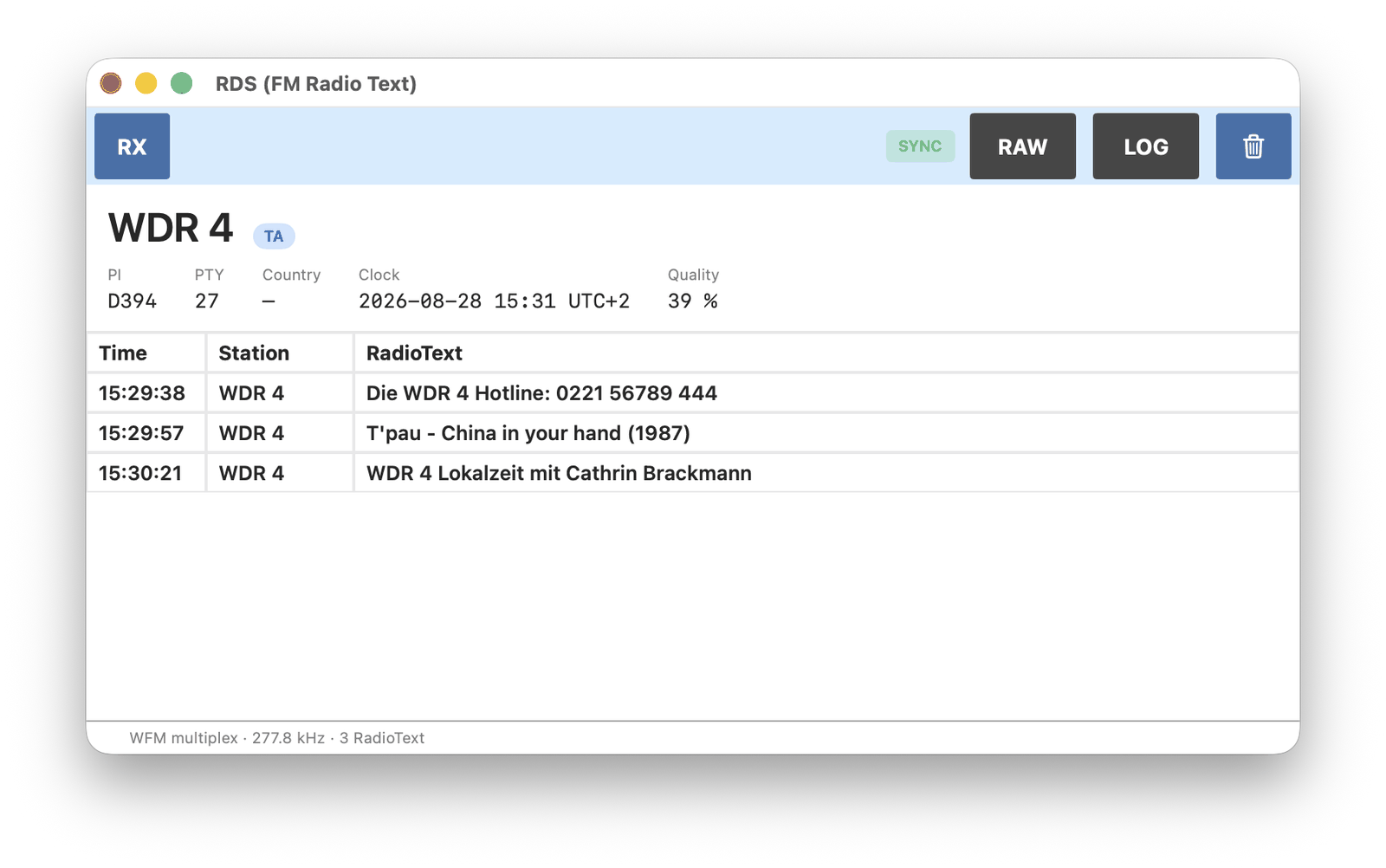
RAW shows the incoming RDS groups as hex instead of RadioText.
13. FT8 (Ham Digital)
FT8 is a weak-signal amateur mode from the WSJT family (Joe Taylor, K1JT). Short messages with callsigns and Maidenhead locators are sent in timed slots. It is used worldwide on HF (and some VHF) to make contacts at low power. This window also decodes FT4 (shorter slots) and FT2.
Each mode has its own published USB frequencies. Select Mode first (FT8, FT4 or FT2), then the band. RX sets USB and starts decoding.
A pass lasts 15 seconds for FT8, 7.5 seconds for FT4, and about 3 seconds for FT2. The bar at the top shows how far the current slot has run. FT8 and FT4 use even and odd UTC slots: even-slot rows are green, odd-slot rows are blue.
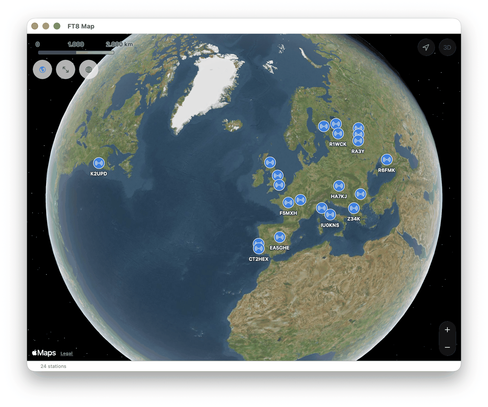
Map shows stations that sent a locator.
14. WSPR (Propagation)
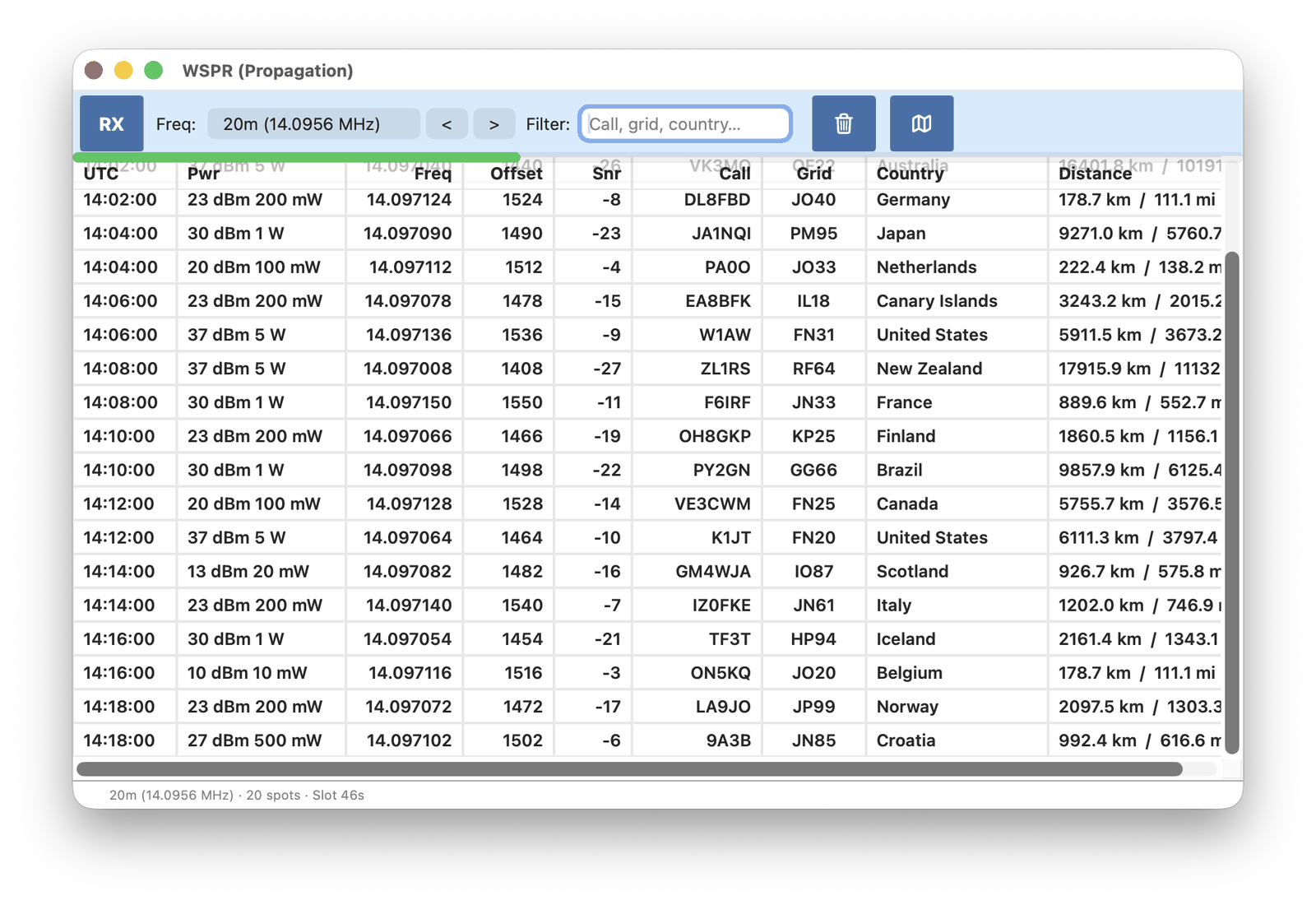
WSPR (Weak Signal Propagation Reporter) is an amateur beacon mode from the same WSJT family as FT8. Stations send a callsign, locator and power at very low power so others can see which bands are open. There is no conversation — only these beacons.
Each pass lasts two minutes (even UTC minutes). The list stays empty until the first slot finishes.
Use Freq to pick a band, then RX. RX sets USB and a 3 kHz bandwidth.
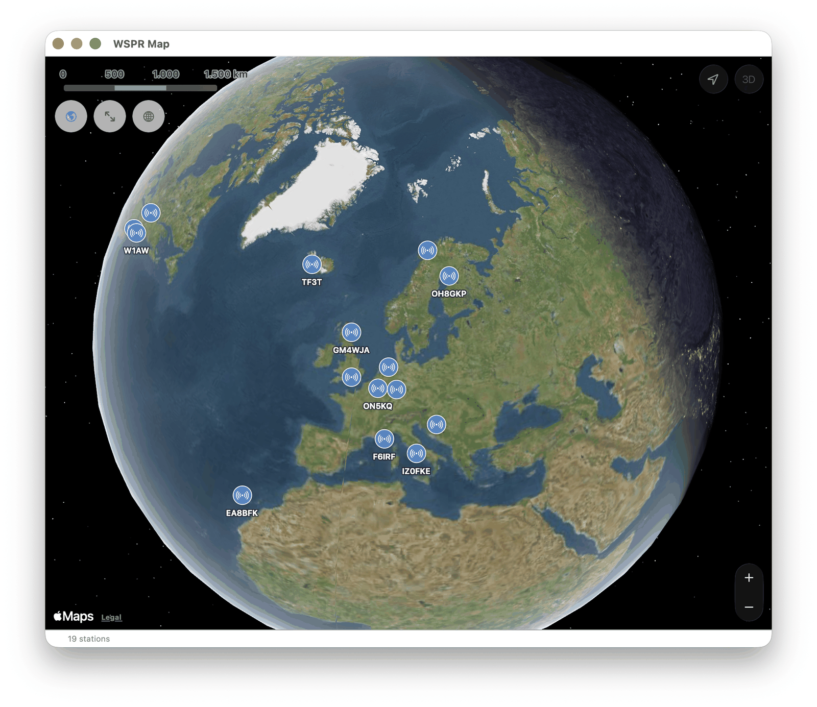
Map shows the stations that were decoded.
15. Time Signal
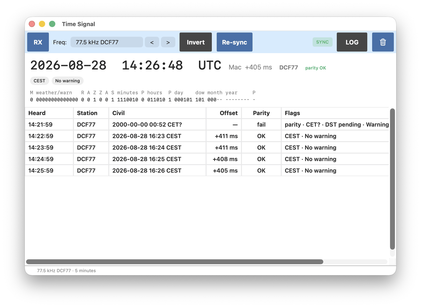
Long-wave time stations send the civil time as a slow stream of bits, once per minute. Clocks and radios use them as a time reference. This decoder covers DCF77 (Germany), MSF (United Kingdom), WWVB (United States), JJY (Japan) and TDF (France).
Use Freq to pick a station, then RX. Bits of the current minute are shown at the top as they arrive. When the minute is complete, a row is added with the decoded time and the offset from the Mac clock.
Stations also send parity bits. If parity fails, that minute may be wrong.
16. Speech / Transcribe / Translate
This decoder transcribes spoken audio and can translate it, so a broadcast in another language can be followed as text.
It uses only Apple on-device speech recognition and translation (Apple Intelligence). Apple Intelligence must be enabled on the Mac. Check SDR-Receiver ▸ Settings…, AI tab.
Tune to a voice station (any mode that produces speech). Select Language, then RX. Squelch should be on so empty audio is not sent to the recognizer.
The upper strip is the live line. It may change while the recognizer is still working. When a segment is finished it is added to the lower part of the window. That lower text is what is logged, and what is translated if Translate is not None.
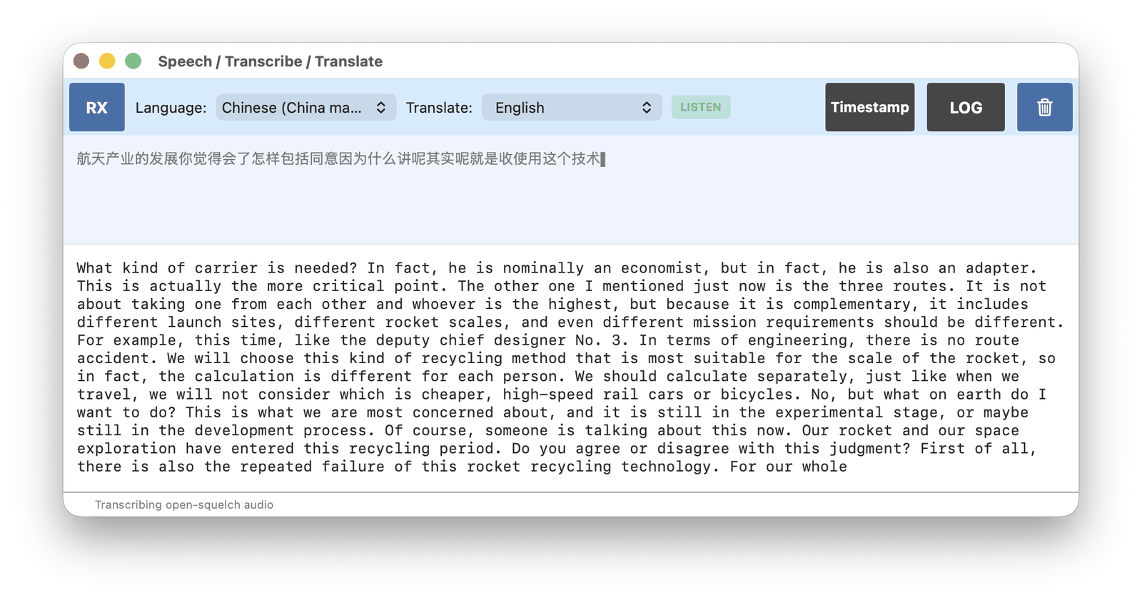
Timestamp starts each new block with a time. LOG writes the finished text to a file.
1. Band Plan
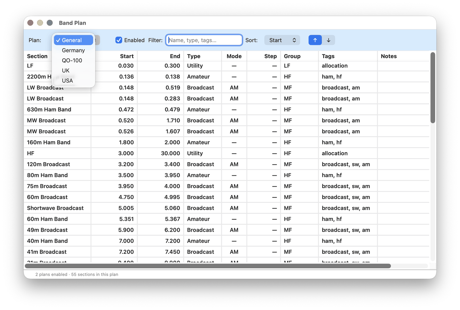
A band plan is a map of frequency ranges: amateur, broadcast, maritime and so on. The app includes a General plan with allocations that are the same in most of the world, plus further plans for regions or special uses.
Open Tools ▸ Band Plan. Enable a plan with its checkbox. Enabled plans appear as the coloured ribbon on the spectrum, so the current range is visible while tuning. The ribbon can also be turned off under DISP.
Band on the main window lists sections from the enabled plans. Selecting a section tunes to its centre and may set the mode.
2. Frequency list
The Frequency List holds reference catalogs of stations, not personal memories. There are no markers on the panadapter for these rows. Show ▸ Stations at VFO lists the catalog entries for the frequency currently tuned. Only catalogs that are Enabled here appear in that window.
The app includes:
General — well-known frequencies that apply in most places
EiBi — a published shortwave broadcast schedule (station names and transmission hours in UTC)
further catalogs that can be created or imported
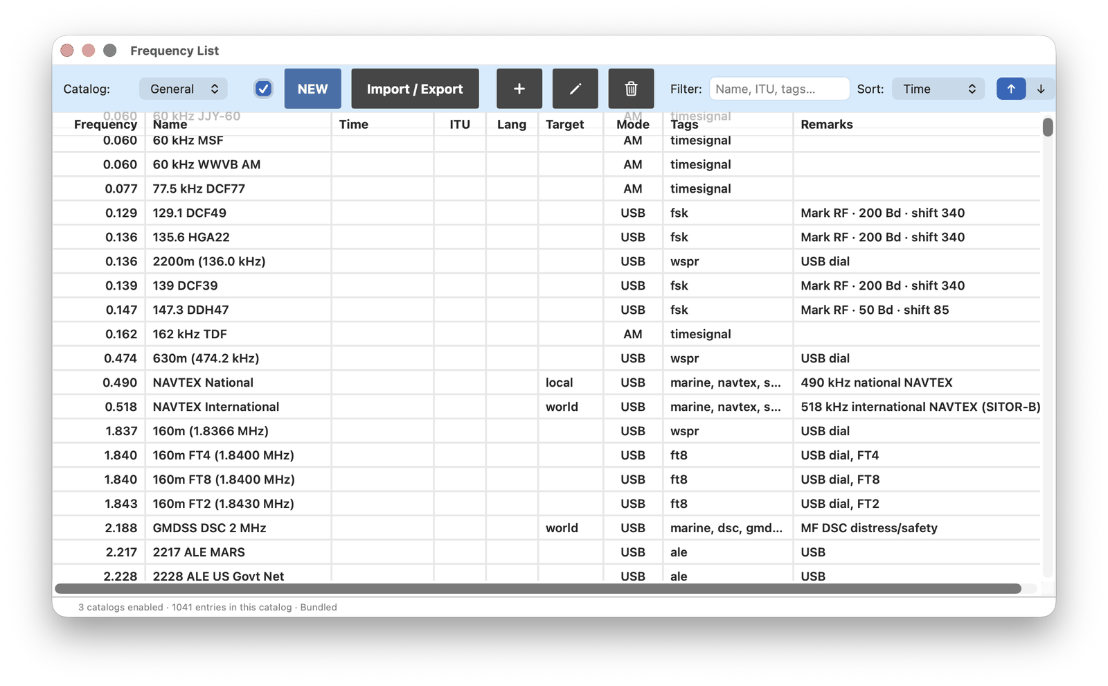
New creates a catalog. Give it a unique ID and a title.
Import / Export can download a fresh EiBi list from eibispace.de (this replaces only the EiBi catalog), import a CSV file into a user catalog, or export a user catalog as CSV.
Add, edit and delete apply to entries in user catalogs. Right-click a row to copy, cut or paste. The same clip can be pasted into Memories, and memories can be pasted here.
Rows outside the range of the connected receiver are shown grey.
3. Memories
Memories are stored channels. Besides frequency they can keep mode, bandwidth, AGC, squelch, step and display span. Bandwidth, squelch and span are optional: if they are not stored, recall leaves the current setting as it is.
A marker is drawn above the frequency scale for each memory. Click a marker to recall it: the receiver tunes to that frequency and applies the stored settings.
Create a memory with M+ on the main window, or from Tools ▸ Memories. The list can be imported and exported as CSV.
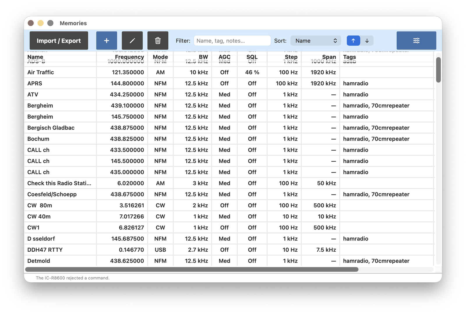
Rows outside the range of the connected receiver are shown grey. Right-click a row to copy, cut or paste. The same clip can be pasted into the Frequency List, and frequency-list rows can be pasted here.
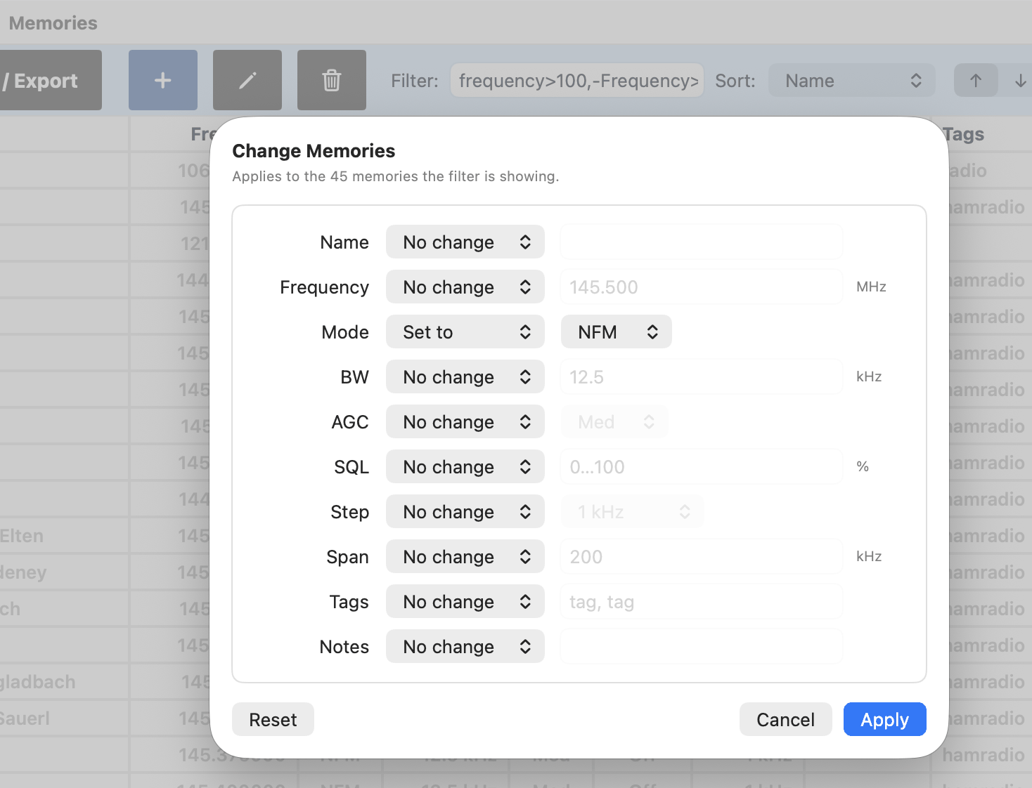
Change applies an edit to every memory the current filter is showing. That is useful for adding a tag to a group of memories, or setting the same mode on a range.
Example: set NFM on all memories between 100 and 200 MHz. First filter with:
frequency>100,-Frequency>200
That keeps frequencies above 100 MHz and hides those above 200 MHz. Then open Change, set Mode to Set NFM, and Apply.
4. Scanner
The Scanner hops through frequencies and records those that are busy.
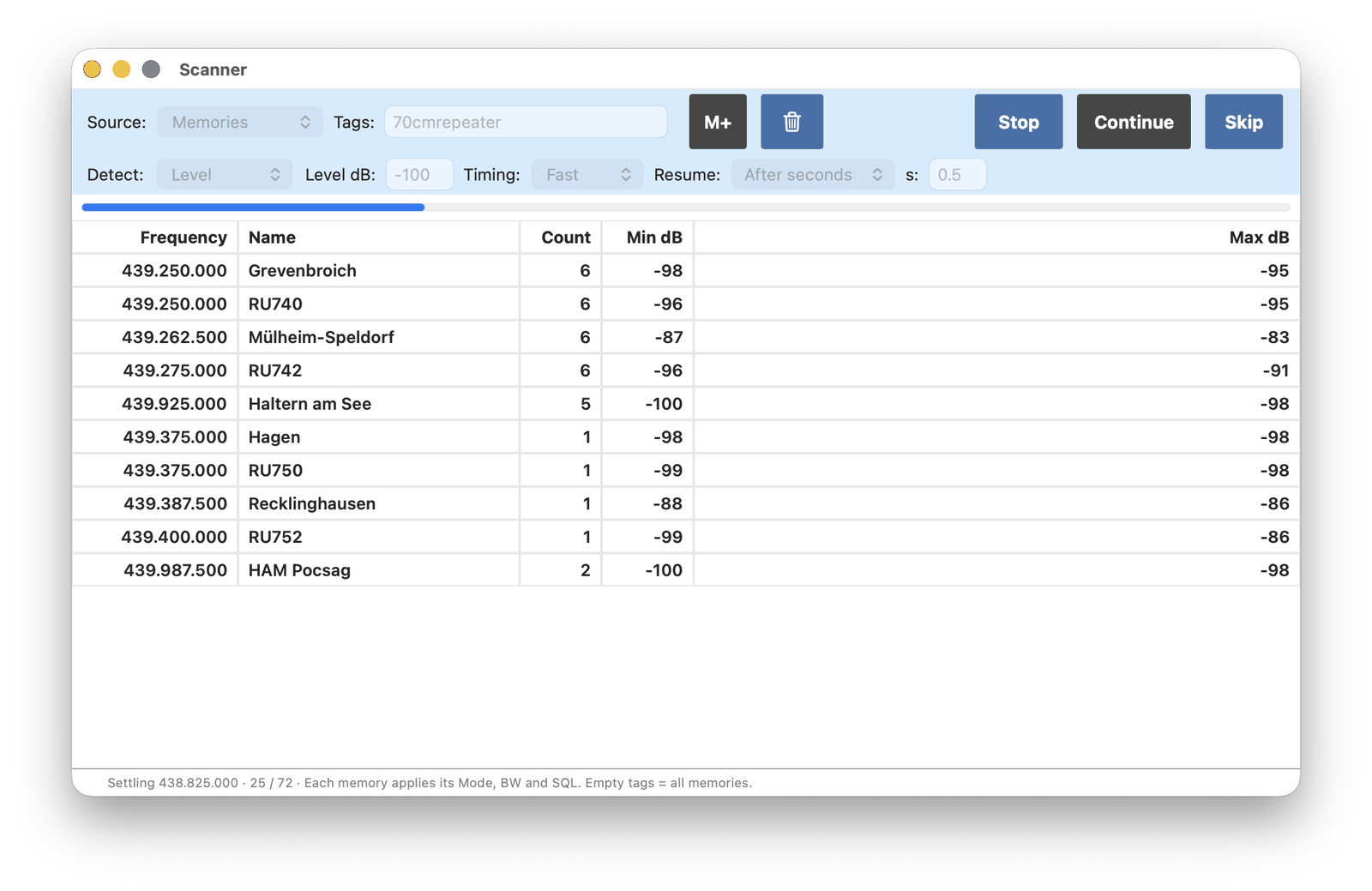
Choose what to scan:
Range — from a start frequency to an end frequency, in a chosen step. The current mode and bandwidth are used.
Preset — a built-in range such as 2 m amateur FM or air-band voice. Selecting a preset also sets mode and bandwidth.
Memories — memories that match a tag filter (empty means all).
Frequency List — entries from the enabled frequency catalogs, also with an optional tag filter.
Detect is either Level (a signal stronger than the entered dB value) or SQL open (the squelch on the main window opens). For SQL open, set squelch on the VFO so it only opens on a busy channel.
Timing is Fast, Medium, Slow or Manual (how long to wait after a hop, and how long to listen). Scanning always runs from low frequency to high.
Resume after a hit:
Stay — remain on that frequency
After silence — move on when the channel has been quiet for the given time
After seconds — move on after the given time even if the channel is still busy
Loop starts again at the beginning of the list. Audio is muted while hopping and restored on a hit or on Stop.
Start begins the scan. Hits appear in the list with a count and the minimum and maximum dB seen on that frequency. Stop ends the scan. Double-click a row to go there. M+ stores the selected hit as a memory. Skip ignores that frequency for the rest of the session. Continue resumes after Stay or a double-click.
5. Audio Recording
Audio Recording writes the speaker audio, not the I/Q stream. What is heard after HPF, LPF, NR and squelch is stored as a WAV file. This is separate from I/Q recording on the main window.
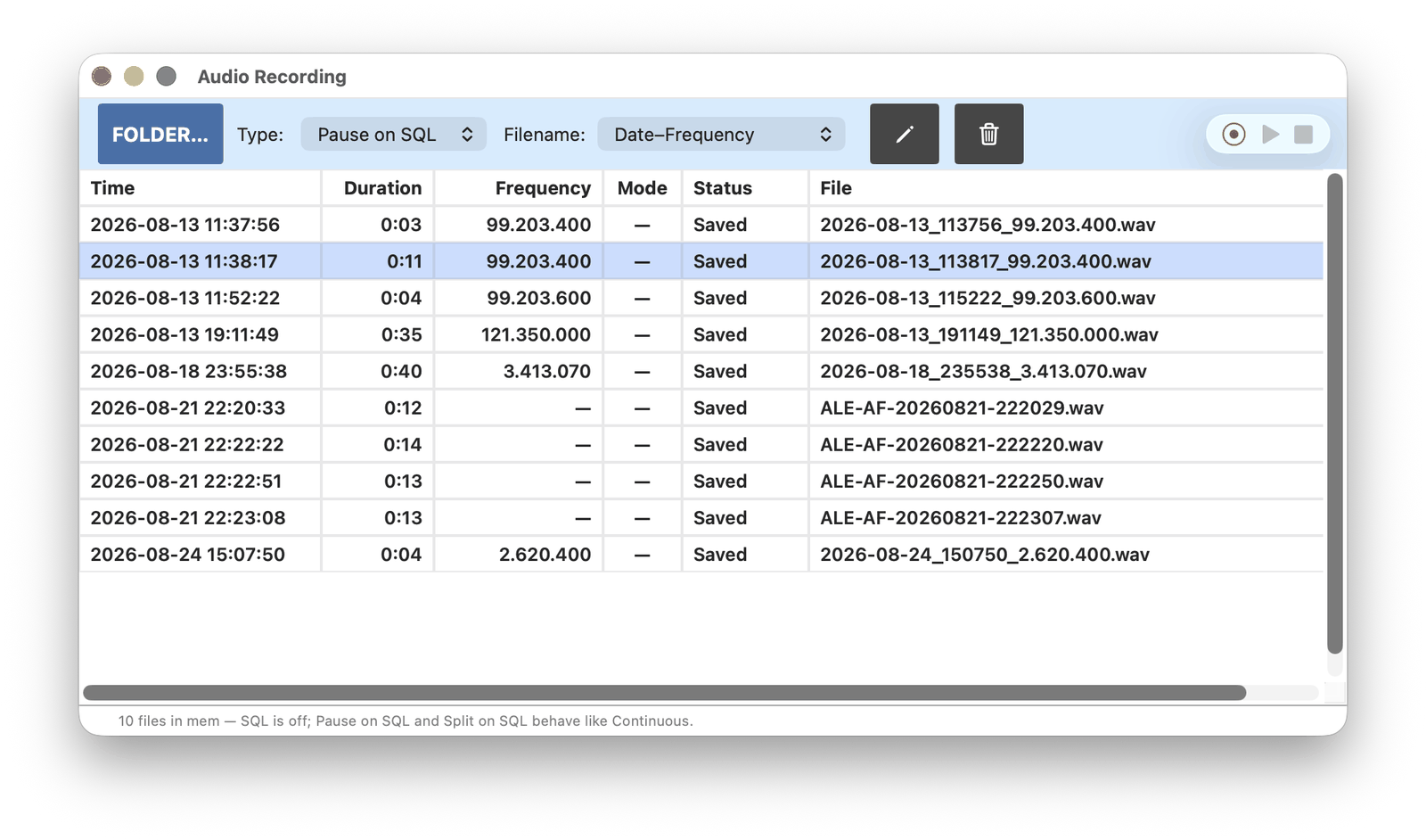
Folder… chooses where files are stored. A folder is required before recording can start.
Type:
Continuous — one file, including quiet periods
Pause on SQL — one file; writing stops while squelch is closed
Split on SQL — a new file each time squelch opens
If squelch is off, Pause and Split behave like Continuous.
Filename patterns can include date, frequency, mode or a sequential number.
Use the recorder controls on the right to start, stop and play. Files in the folder appear in the list. A row can be played, renamed or deleted. Very short captures are discarded.
1. Stations at VFO
Show ▸ Stations at VFO lists frequency-list entries for the frequency currently tuned. Memories can show a marker on the spectrum; a frequency list often has several stations on the same channel, so a list is used instead of markers. The window can stay open while tuning.
Only catalogs that are Enabled in the Frequency List appear here.
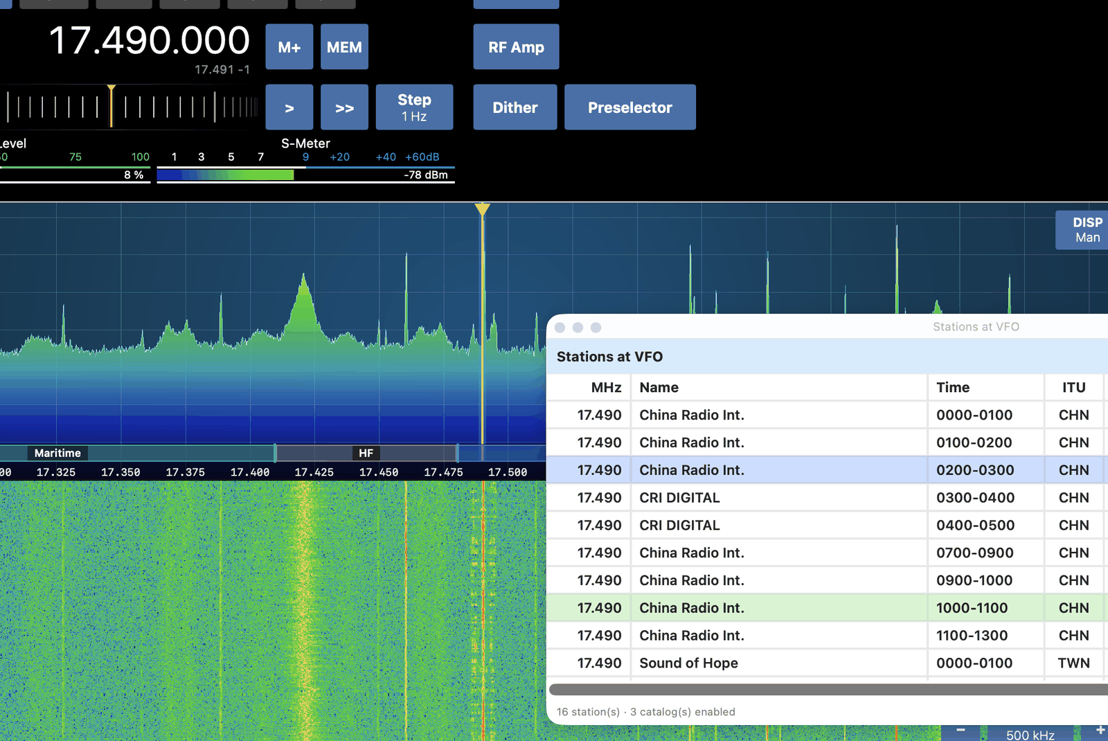
If an entry has operating hours, it is highlighted green when those hours include the current time. Hours are always UTC. The UTC clock at the top of the main window is the reference.
Double-click a row to tune to that station.
2. Tune Stack
Show ▸ Tune Stack remembers frequencies visited in this session. Panning the display without changing the VFO does not add an entry.
Stay on a frequency for a few seconds and it is pushed onto the stack, with the demodulation mode. The stack holds the last ten. Click a row, or use the up and down buttons, to return there.
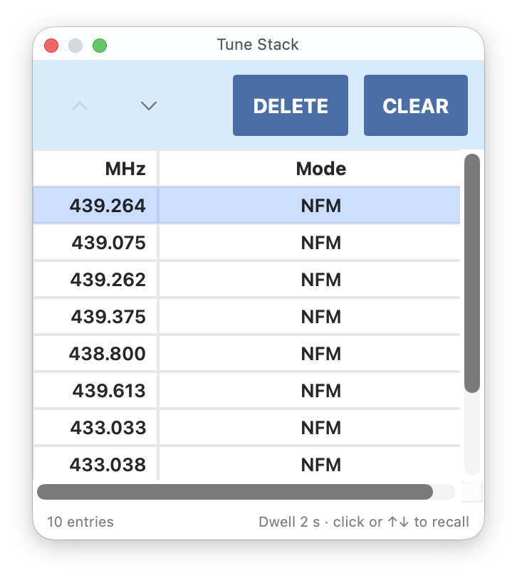
DELETE removes the selected entry. CLEAR empties the stack. The list is not kept after the app is quit.
Common Issues
Stuttering audio or waterfall
If the audio or the waterfall stutters, connect the receiver directly to the Mac, not through a USB hub. Try a different USB port.
Latest version
Keep both the app and macOS up to date. The app requires macOS 26 or later.
Check for Update under SDR-Receiver ▸ Settings…, Support, looks for a newer version.
What changed in this version
After an update, What’s New appears once, listing what that version added. It can be dismissed for good, and it can always be reopened from SDR-Receiver ▸ Settings…, Support.
Version History, in the same place, lists the notes for every release rather than only the current one. It is the quickest way to find out when a control appeared, or whether a change that is being looked for is in the installed version at all.
Getting in touch
If the problem remains, use Contact Support in the app (Help menu, or SDR-Receiver ▸ Settings… then Support).