SDR-Control for macOS - Software user guide
1. About the App
SDR-Control for macOS is an App for your Mac to operate your Icom Radio via network.
1.1. Operate in any Mode
You can operate in SSB using the mac internal Microphone or use a Headset like Apple’s AirPods or another Bluetooth or USB Headset. You can also operate in CW using the integrated Keyer and CW decoder. Furthermore, you can operate in FT8/FT4, RTTY and other modes using the integrated decoding tools. Operating in these modes no longer requires external Software and cables. But if you wish, you can still use such external software because this App also integrates a CAT Server and supports the Common-Radio™ Audio interface, ensuring rapid and low-latency audio transmission. This feature is also explained in details under External Software.
1.2. Local or Remote
Besides the possibility to connect to your Radio on your home network, where your Radio is located, SDR-Control also supports Remote Access to your Radio from around the world without the need for additional Hardware or Software. No Server is needed. It works, just with your Icom Radio. The only requirement is a Icom Radio that offers a network interface like the IC-705, IC-9700, IC-7610, IC-7760, IC-R8600 or IC-7300 MK2. Remote access using an IC-7300 is not possible as it only provides a USB connection.
Note
The App displays and can send back most values and settings to and from the Icom Radio. Some values (like the VFO Frequency and Waterfall) are exchanged real-time. Others needs to be polled from the Radio in regular intervals. For this reason, if you would use the physical controls of the Radio (except for the main frequency dial), changes are not or not immediately available to the App. Ideally, solely use the controls from inside this App.
1.3. Troubleshooting
In case of problems, please first have a look to the Common Issues section of the manual. If you can’t find any help there, please use the App included Contact Developer feature to contact me and I will be happy to help.
2. The manual
This manual explains how to setup your Icom Radio and the App and how to work with the App. Where possible and where it makes sense, the App uses the same abbreviations and terms for buttons and menus that are used by Icom for physical knobs and Buttons on the Touch screen. Those terms such as “P.Amp” (for Pre Amplifier) will not be explained in this manual because they can be looked up in the regular Icom manual.
This manual can be opened from inside the App or directly following this link: https://go-to.me/sdrcontrol-manual .
If you prefer a printed version, just tap here. This can also be used to save a PDF file of the Manual.
But please keep in mind, that this manual will be updated from time to time.
2.1. Videos
In addition to the manual and for those who don’t like to read manuals, there are also a few videos from popular HAM Radio bloggers in English and German at the bottom of the App’s website: ham-radio-apps.com
3. Requirements
SDR Control for Icom can be used for the following Icom Radios:
IC-705 (via WiFi or USB)
IC-9700 (via LAN cable or USB)
IC-7610 (via LAN cable or USB)
IC-7760 (via LAN cable)
IC-R8600 (via LAN cable or USB)
IC-7300mk2 (via LAN cable or USB)
IC-7300 (via USB)
Note
USB is much slower than LAN or WiFi
Any of the Radios can be connected to your Mac using a USB Cable. However, a USB connection is slower so a LAN connection would be preferred. This means that the Radio should be connected to your local network using a LAN cable. The IC-705 only offers WiFi so it needs to be connected to your local network using WiFi. The IC-7300 only supports a USB cable.
Your Mac also needs to be connected to the local network, ideally also using a LAN cable but WiFi will work as well. When using WiFi, ensure you have a fast and stable WiFi connection.
The App doesn’t have any relevant RAM or Hard-drive space requirements. It runs natively on both Intel and Silicon Mx Macs.
The App requires at least macOS Sonoma (macOS 14) or newer.
The newest macOS Version is always preferred as the App takes advantage of some features only available in the newest macOS version.
If you have purchased the App once on the AppStore (thank you!) you can run it on several additional devices with any number of Icom Radios you own. No additional purchase is necessary. You only have to use one and the same Apple ID on all your devices.
4. Setting everything up
In order to use the App, you first need to setup your Icom Radio as described further below. Once that’s done, you can add your Radio to the list of Devices of the App and connect to it.
4.1. Setting up the Radio
Your Icom Radio needs just some basic setup to allow this App to connect to it.
For the Network supporting Radios, the Radio must be setup to connect to your local Network (via LAN Cable for the IC-7610, IC-7760, IC-9700, IC-7300mk2 or IC-R8600 or WiFi for the IC-705) also the Radio setting “Network Control” needs to be enabled, and a username / password must be set in your Radio settings.
For the old IC-7300 which doesn’t support network connections or in case you want to intentionally use a USB connection, only a few necessary USB settings must be set.
Detailed setup instructions of your Radio can be found in the attachment of this manual for all supported Icom Radios. Even if you already setup your Radio, please have a look to the setup instructions, specific for the Radio as well as the Network Considerations further below in this manual. A separate chapter Remote Access explains how to access your Icom Radio even from around the world, outside your home network.
Hint
If you have issues setting up your Radio, please have a look to the Common Issues chapter of this manual.
4.2. Adding the Radio to the App (Network)
After setting up your Icom Radio for Network access as described in the Attachment, start the App.
Note
If you see the message that asks for permission to use the microphone, please confirm this message with Ok as well as a possible message about a recent update.
Next click on Connect or the center of the Screen. The Radio chooser will appear with an empty list. Now click on Add to add information about your Icom Radio:
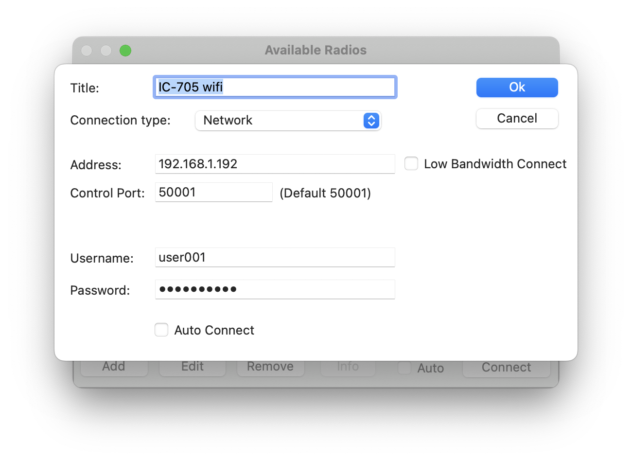
Here, you need to select Network as Connection type and enter the information you have collected during the Radio setup as described before. You can also enter a Title for your Radio.
The Low Bandwidth Connect feature is designed to minimize network traffic. This option is particularly useful when operating on unstable or slow network connections. However, if you’re on a stable and high-speed local network, you may choose to disable this setting.
The Auto Connect feature offers added convenience, especially if you operate just one radio. When this option is enabled, the app bypasses the “Available Radio” screen and automatically connects to your designated radio.
Important
Exercise caution when using the Auto Connect feature. Ensure that your radio is configured to maintain a consistent IP address. If the IP address of the radio changes, the app will be unable to establish an automatic connection. Should this occur, consult the ‘Common Issues’ section of this manual for troubleshooting guidance.
Once you click on Ok and back on the previous screen you will find your newly added Radio in the list.
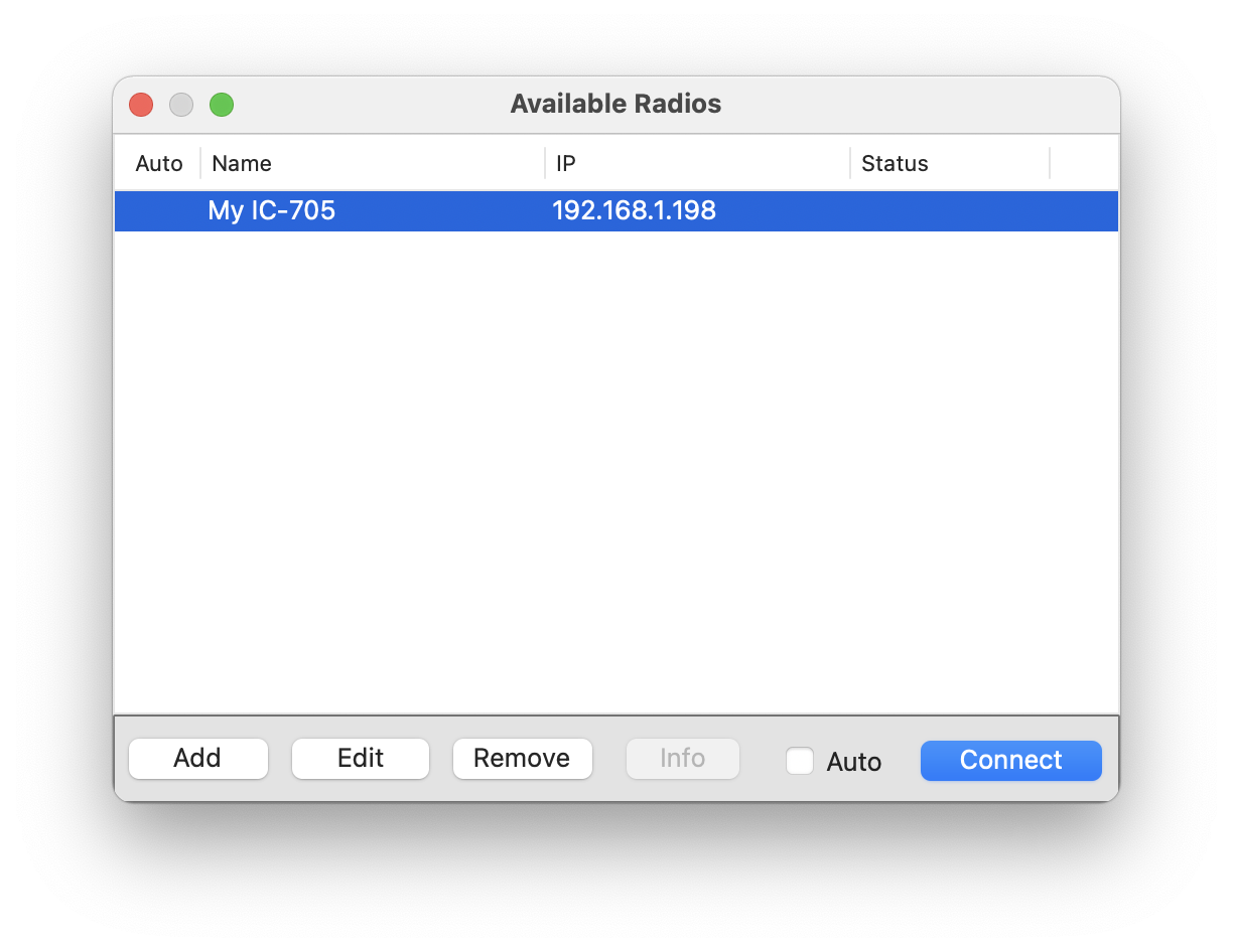
To connect to your Radio, just select (highlight) the entry and click on Connect – or double click on the line in the list.
4.3. Adding the Radio to the App (USB)
If you are using a USB cable instead of your Network to connect to your Radio, you setup the Radio USB Settings as described in the Attachment of this manual. In this case, all Radios need to be setup in the same way as described for the IC-7300.
Next, connect the USB Cable between your Mac and your Radio and start your Radio and the App.
Note
If you see the message that asks for permission to use the microphone, please confirm this message with Ok as well as a possible message about a recent update.
Once you connect the USB cable to your Radio and your Mac, there will be three new Devices available on your Mac which is a new Serial device and two new audio devices.
Next click on Connect or the center of the Screen. The Radio chooser will appear with an empty list. Now click on Add to add information about your Icom Radio:
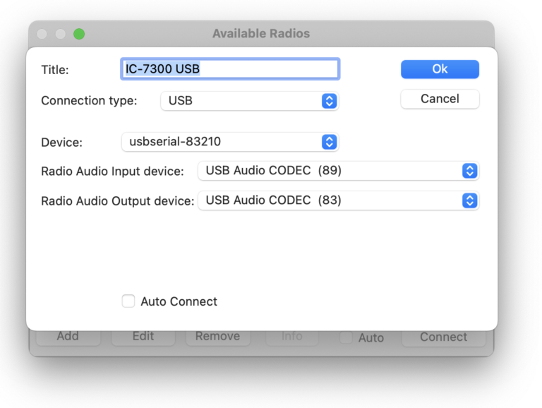
Select USB as Connection type.
Next you need to select the serial device for the Device: selection. The difficulty here is, that the name of this device may differ and is not related to your Radio’s name. If you are in doubt which device to select, just disconnect the USB cable, reconnect and see which device has been added after re-connecting the cable again. If you have additional Radios connected via USB it may even happen that they are called the same.
Audio is transferred from and to the Radio by two newly created audio devices for your Radio. Unfortunately, like for the serial device, the device names are not related to the Icom Radio and you may also need to find the correct device by experimenting with disconnecting and re-connecting the USB cable.
In any case, the correct three devices (serial and input and output audio) need to be selected in order to be able to access and use your Radio by the App.
Once your USB Radio has been added, you can proceed to connect to it just like explained before for a Network Radio.
Hint
If you have trouble to get the IC-7300 working, please check the common issues section further below of this manual.
4.4. Final settings (Important!)
Once you can connect to your Radio, don’t forget to adjust your ALC level as described further below. This setting can be found under Radio, IC-xxxx menu.
Second, you may want to decide how the App should leave the Radio after disconnecting. The App just changes a few settings but depending on how you want to use your Radio without the App, you need to decide which settings should be reverted after the App disconnects. These settings can also be found under the Radio, IC-xxxx menu after being connected.
Finally, in case you are using a Network connection, use the Network Stats Tool (under Tools) to see if you have a good network connection to your Radio. You should always have an error rate below 0.05% for a smooth operation. If the error rate is higher, you need to investigate for your network problems (see the common issues section for further help).
5. The Main Window
After connecting to your radio, you will see the main window which includes all the frequently used functions for controlling the radio and the waterfall display, as shown below:
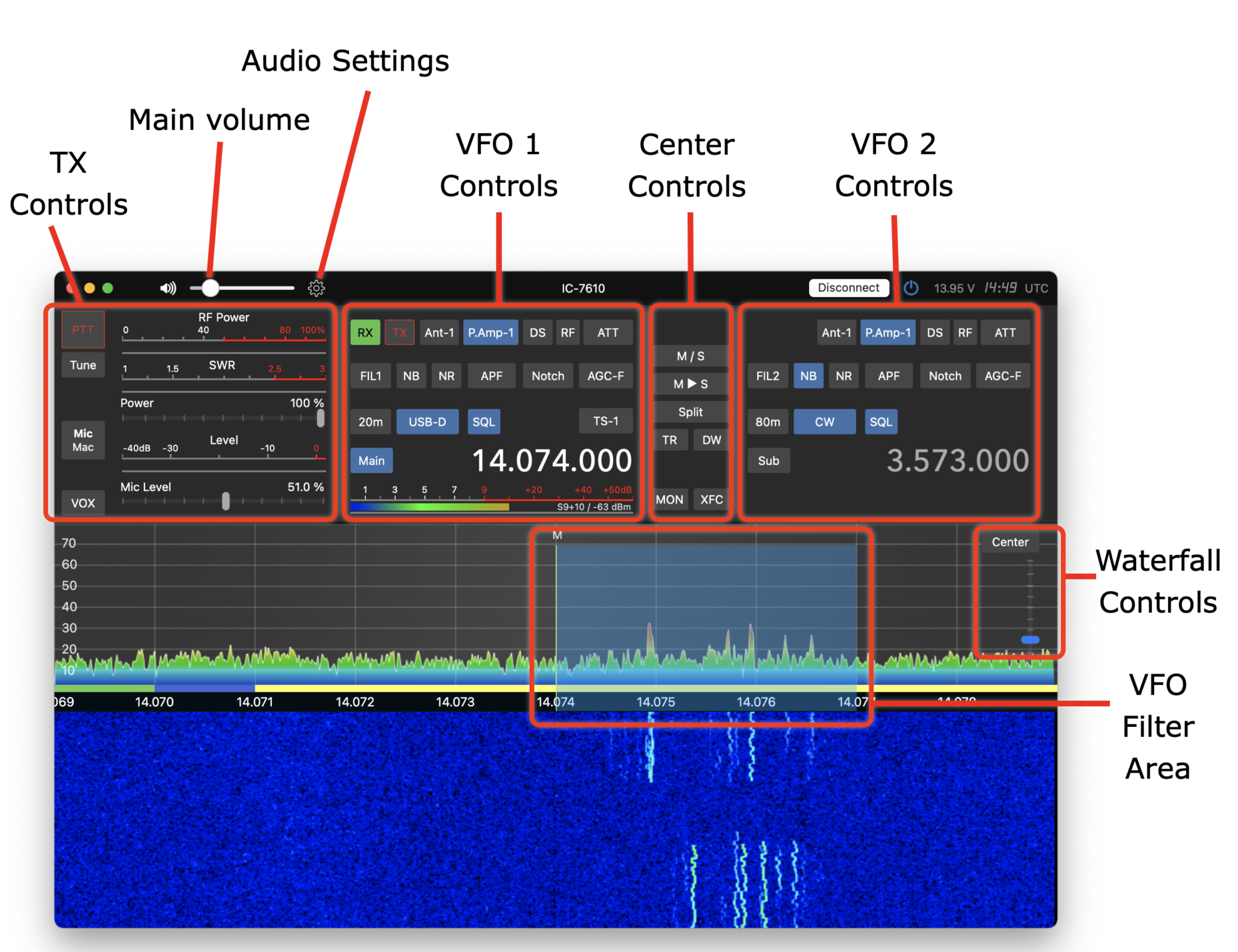
The main window is divided into various sections, each with buttons, sliders, and meters.
Most buttons are labeled the same and function similarly to the physical or software buttons on the radio, and for this reason, they are not explained here in detail. Other buttons are unique to the app and will be explained below.
5.1. Buttons left and right clicking
Some buttons offer two actions. They can be (regular) left-clicked to quickly change a certain setting and to perform a certain function. For instance hitting PTT once will start transmission, hitting it again will end transmission or a quick selection like the FIL buttons where you can quickly select one of the three filters.
Additionally, some buttons can be right-clicked (using the secondary mouse button) to access further settings related to that button. For instance, if you right-click the aforementioned FIL button, detail filter options can be maintained:

5.2. TX Controls
The Tune button tuning feature can only be used if your Radio has an Antenna tuner included or if a tuner is attached to it. However, right-clicking on Tune can be used to generate a 10% AM signal even without using a Tuner. A framed Tune button indicates an active tuner.
The Mic button needs to be used to define the microphone input source for your Radio. The available sources can be selected by right-clicking this button. To use your local Mac (either the internal microphone Headset connected to your Mac) as microphone source, chose Net as selection (or USB in case your Radio is connected via USB). Also, double check your Microphone selection in the top Audio menu (gear Icon).
Note
When selecting Net or USB as Microphone source, you will see a dedicated audio level meter otherwise the Radio Compression meter will be displayed. Compression and Anti-VOX is not available when using your Mac as microphone source.
Right-clicking the power meter offers the option to replace this meter by the ALC or ID meter.
5.3. VFO 1 and 2 Controls
Depending on the VFO Mode and Radio model, the two VFOs are either called VFO A and B or Main and Sub.
Some Radios like the IC-7610 allows maintaining the settings of both VFOs at the same time. For others this is only possible for the currently active VFO. In that case, either click on the Main / Sub or VFO A / B buttons or on the VFO frequency to activate one of the two VFOs. All available buttons will get visible for the selected VFO and can be maintained as usual.
Right-clicking on the Frequency offers a screen for direct frequency input. Keep in mind that it must either be a frequency in MHz or kHz depending on the App setting.
5.4. Center Controls
These buttons are also similar to the buttons available on your Radio and are mainly responsible for the relation between the left and right VFO. For instance the M/S (or A/B in VFO Mode) will swap the left and right VFO.
Some buttons like SAT (for Satellite Mode on an IC-9700) or TR (for Tracking mode on an IC-7610) are only available for Radios supporting this function.
5.5. Waterfall Controls and the Waterfall
The slider on the top right side of the Waterfall section can be used to adjust the waterfall reference level.
Hitting the button left from this slider let you chose the Waterfall mode like Center, Scroll-F, Scroll-C or Hold.
In addition, right-clicking this button will show additional Waterfall settings.
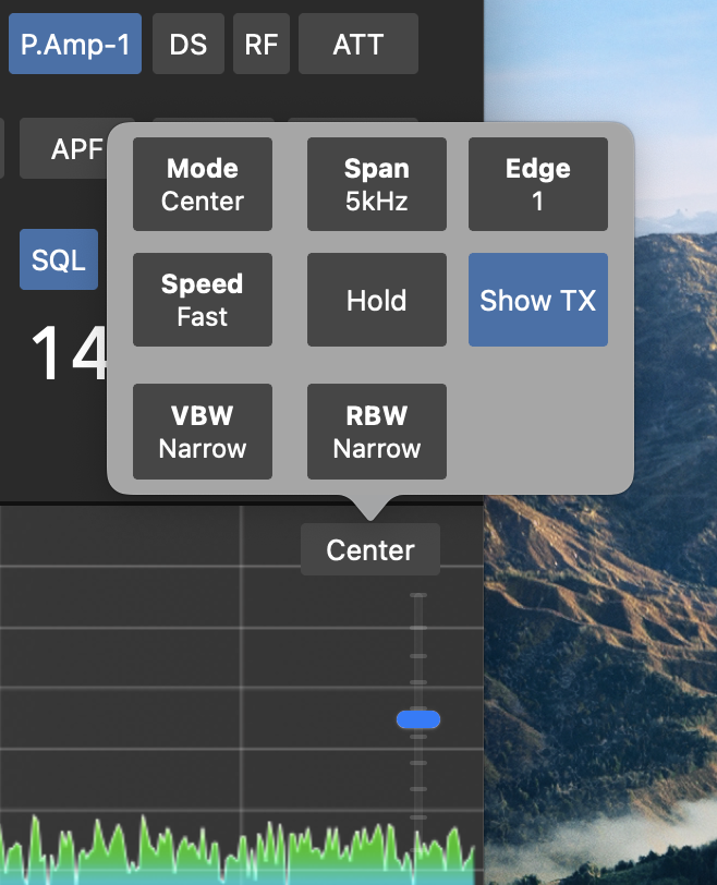
Note
Waterfall fixed mode is not supported.
Note
Depending on the Radio capabilities, some features are not available in all Waterfall modes. For example, the Show TX setting only works in Center mode.
Further details are explained further below in the Frequency Tuning section of this Manual.
6. Supplemental Windows
In addition to the Main Window, you can open (and keep open) various supplemental windows through the View menu for enhanced operation.
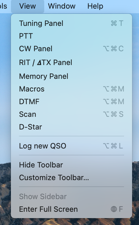
These supplemental windows include, for instance, a separate Tuning Panel, RIT/XIT Panel, Memory Panel, Macro Quick Access buttons, and a DTMF Panel for sending DTMF tones or triggering a Repeater 1750 Hz signal.
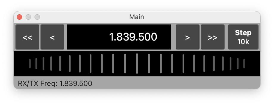
Use the Tuning Panel Window to precisely adjust the VFO frequency:
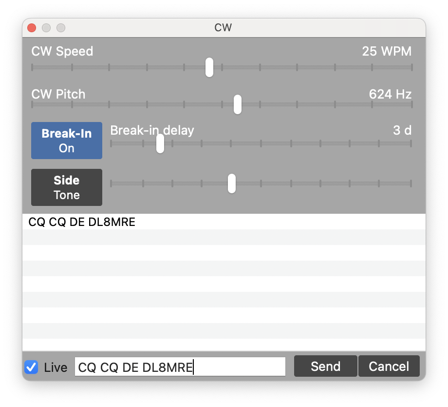
This Window can be used to send CW:
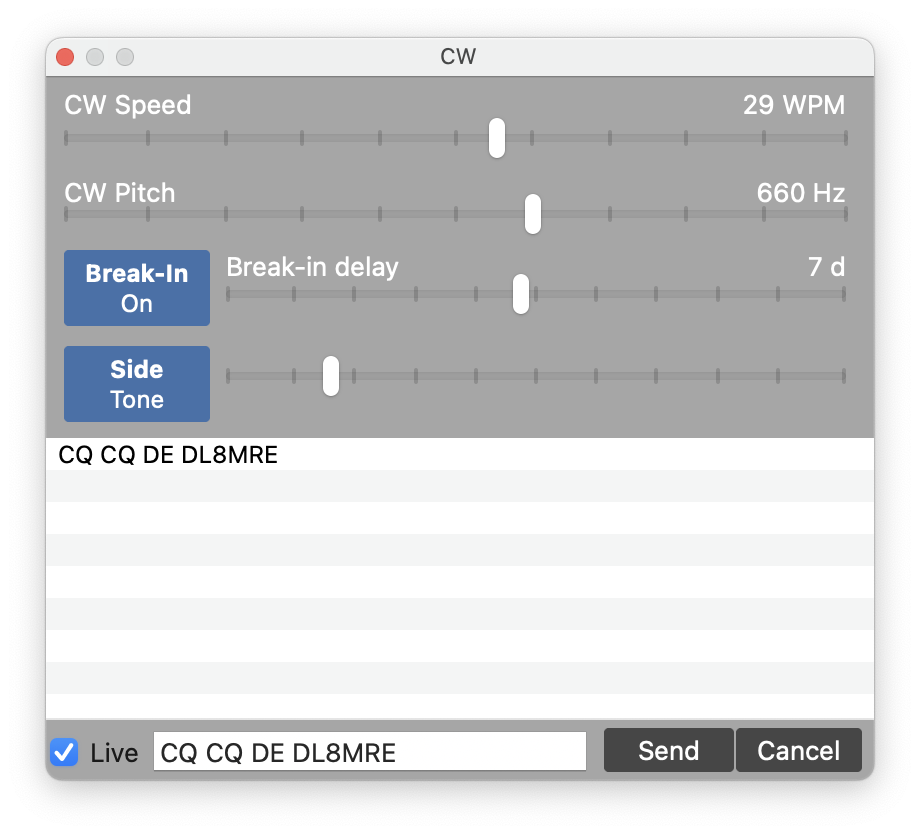
Note
You can send pro-signs like BK by using the ^ prefix character (e.g. ^BK). pro-signs can not be send in live mode but can also used in CW Macros.
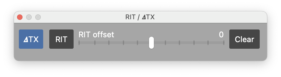
This Window can be used to operate in Rit / Xit mode:
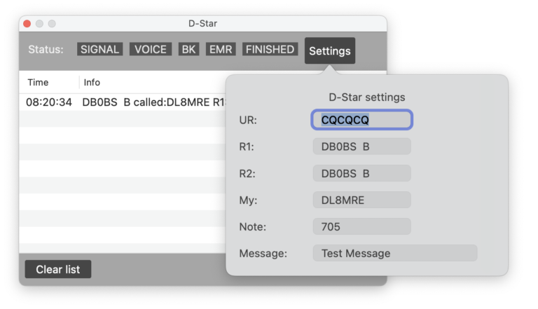
For Radios supporting D-Star (DV) this Window displays the current D-Star status and displays received messages. From here, you can also set your D-Star settings.
7. Settings
In this App, you can maintain different types of Settings. First, there are general App Settings which are App and not Radio specific such as your HAM Radio information like Call-sign, Country, Locator etc. and your credentials for the integrated Call-Sign lookup features. These settings can be maintained from the SDR-Control, Settings Menu. Second, there are Radio specific settings which can only be maintained, once you are connected to a Radio. In this case, you will see another Radio menu at the top and a IC-xxxx submenu names according your Radio type which can be used to maintain the Radio settings.
And finally, there are the Audio settings which can be used to define your Microphone and Speaker source and volume.
7.1. App settings
The App settings can be found under the SDR-Control menu.
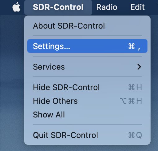
Note
In macOS Versions prior to Ventura, the Settings menu is called Preferences
As mentioned before, the settings here depend on the Radio you are using and currently connected to.
Most of these settings are self-explanatory. It might be worth to go though these settings and add / select your personal information and preferences.
In the “Information & Support” section, you can find the “Contact Developer” button in case you have questions or issues.
7.2. Radio settings
As mentioned before, the settings here depend on the Radio you are using and currently connected to.
The content of the Radio settings and the available options depend on the capabilities of the connected Radio.
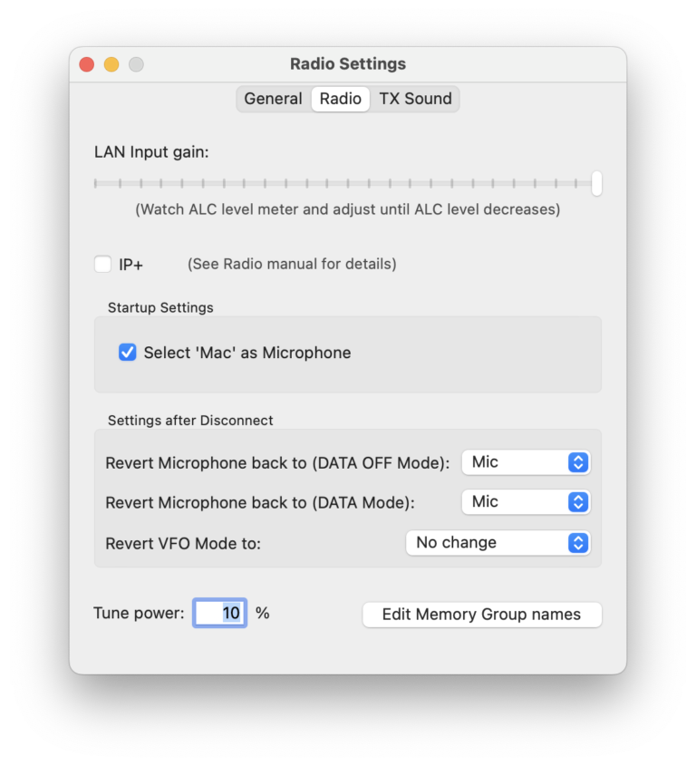
An important setting here is the LAN input gain slider. Before you start working in digital modes like FT8 using the App you will need to maintain this gain slider for a correct audio signal. For this, look for a free frequency and start transmitting in FT8 (e.g. by calling CQ) and move this slider up from the lower position until the ALC meter no longer increases. For this, you can either watch the ALC meter on your Radio (as this must only be done once) or you can change the Power Meter of the App to display the ALC meter by right-clicking the power meter.
Under “Startup Settings” you are able to force the Mac as Microphone to be activated upon App connection.
Under “Settings after Disconnect” you can decide how the App should leave your Radio once you disconnect from the Radio. If you want to use your Radio with the locally connected Microphone once you are no longer using the App, you can select “Mic” for DATA ON and/or OFF mode for example. So if you forgot to change the Mic setting back from inside the App, this setting will ensure that you can use the locally connected Microphone after disconnecting.
You may see additional setting options here on the Radio settings screen depending on the capabilities of your Radio.
For instance, the IC-9700 offers a SAT mode so for this type of Radio you will see a button to maintain your SAT settings which are explained further in a separate chapter below.
For Radios that are providing Memory groups you can also maintain Memory group names.
Note
If you have already maintained Memory Group names on your Radio, Icom doesn’t offer these names to remote Apps so you will have to enter the names again here for the App.
For Radios that are supporting different DATA channels like the IC-7610, under DATA MODE you can select whether DATA 1, DATA 2 or DATA 3 should be used.
7.3. Audio settings
The Audio Settings can be reached by clicking the top gear Icon.

From here, you can decide where audio (speaker output) should go to and where microphone input should come from.
Note
The audio settings within this app operate independently of your Mac’s general audio settings. This flexibility allows you to route system sounds through your Mac’s internal speaker while directing radio audio to a separate speaker. Thus, there’s no need to alter your System Audio settings; all adjustments can be made directly within this app’s settings screen.
If your setup lacks a microphone (as is the case with Mac Mini, which doesn’t come with an internal microphone), you have the option to uncheck “Enable Input Device.”
The Mic Threshold slider lets you mitigate ambient noise interference. Simply raise the slider to the desired level to filter out unwanted background noise.
Located at the bottom of the settings screen, you will find options for enabling and adjusting the volume of the radio’s internal speaker.
Should you experience audio dropouts, consider modifying the Buffer Size setting to improve performance.
Attention
This app is compatible with USB or Bluetooth headsets and speakers. However, you must specify your preferred audio device within the app’s Audio settings screen. Remember, these settings are distinct from your Mac’s System Audio settings. This separation enables you to, for example, use your Mac’s built-in speakers for general audio tasks (like web browsing and system notifications) while allocating a different device solely for radio usage.
Note
If you notice static noise at the beginning of your transmission, activating the Mic Delay setting may resolve the issue. This static is typically residual receive noise captured by the microphone as you start transmitting. If you’re using a headset, this option is generally not necessary and can remain disabled.
8. Frequency Tuning
Frequency tuning is probably one of the main activities when using the App. For this reason, there are several possibilities for frequency tuning:
In Center mode: Move the waterfall to change the Center Frequency. Just click somewhere at the waterfall, hold the mouser down and move to the left or right
In Scroll-F or Scroll-C mode: click-hold and move the VFO Frequency (the yellow line) to left or right.
Double-click somewhere on the waterfall to move the currently active VFO to that frequency
Use the Mouse scroll wheel to adjust the frequency
Click on the VFO Frequency and get an input screen to enter a frequency manually
Use the supplemental Tuning Panel window to fine tune a frequency (View Menu → Tuning Panel)
Here you can use the <<, <, > or >> buttons to tune the frequency down or up based on the Step settings.
You can use the tuning wheel for tuning as well. Depending on your personal preference, you can reverse the wheel direction in the App settings.
In addition, you can also tune the frequency by
The physical VFO knob at the Transceiver
Attach a MIDI controller such as the DJ2GO2 to your iPad via USB cable and use it for frequency tuning and more
Assign keyboard keys (see Tools section of the App) for additional tuning options
9. Memories
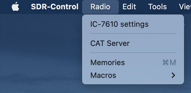
Memories can be maintained, exported and imported from the Radio → Memories menu.
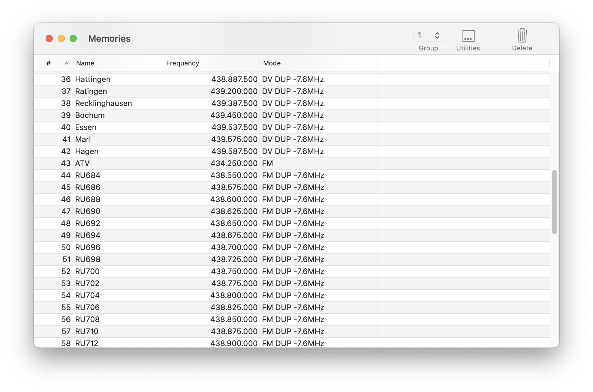
By double-clicking a line, you can enter or alter all available memory fields.
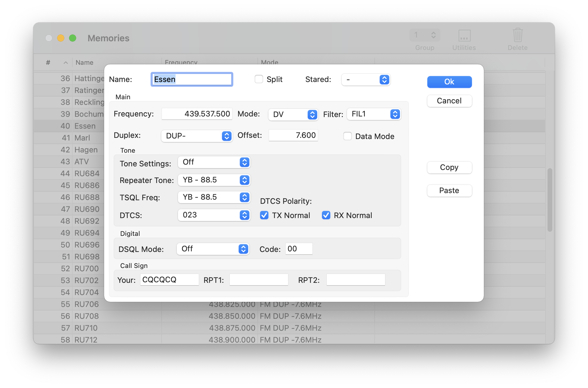
The available entries of this detail view depends on the Radio. Also, the number of available channels and memory Groups. For the IC-9700 there are basically no separate Memory Groups available because each of the three Groups are always already dedicated for a certain band.
To Export and Import Memories, just hit the top Utilities button.
Using this feature, you can exchange Memory settings between different Icom Transceivers. All fields that are not available in a certain Transceiver will just be ignored.
Import and Export always applies to selected Group so you can use Import and Export also to transfer the contents of one Group to another.
When maintaining memories, it is important to only use values valid for the Transceiver. For instance, if you would enter a Frequency, that is not supported by a Transceiver, such a Memory will not be accepted by the Transceiver.
You can use the supplemental Memory Window to quickly access or maintain memories.
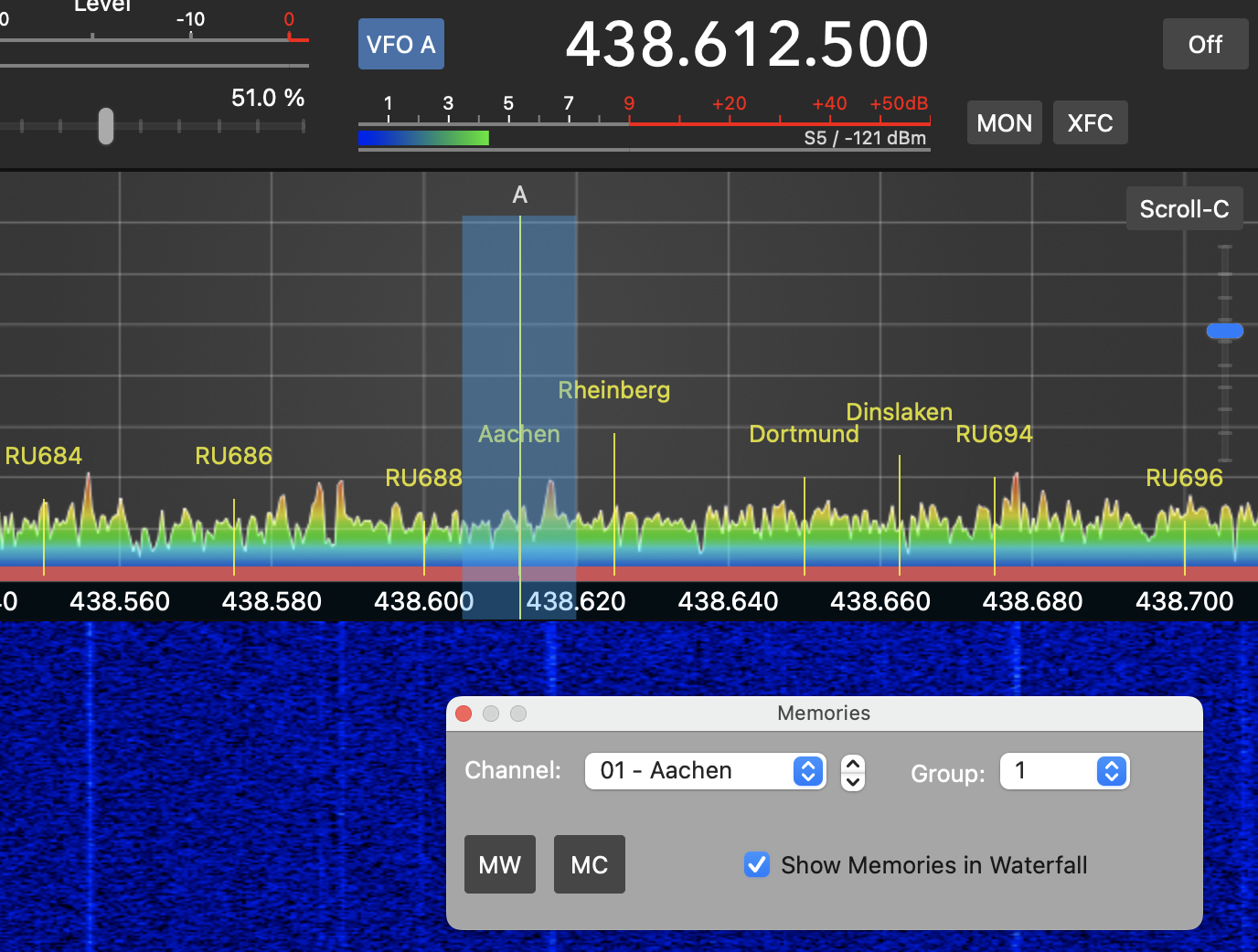
Using the MW button, the current frequency can be stored to a certain Memory channel and given a name.
The MC button will clear the currently selected Memory channel.
The Show Memories in Waterfall option will, if enabled, display the Memory names at the frequency location in the waterfall as shown above. You can adjust the position and font size of these Memory-Spots in the App Settings.
10. Macros
It is possible to create CW-, RTTY, PSK- and Voice Macros. For maintaining your Macros, use the Radio → Macros sub-menus.
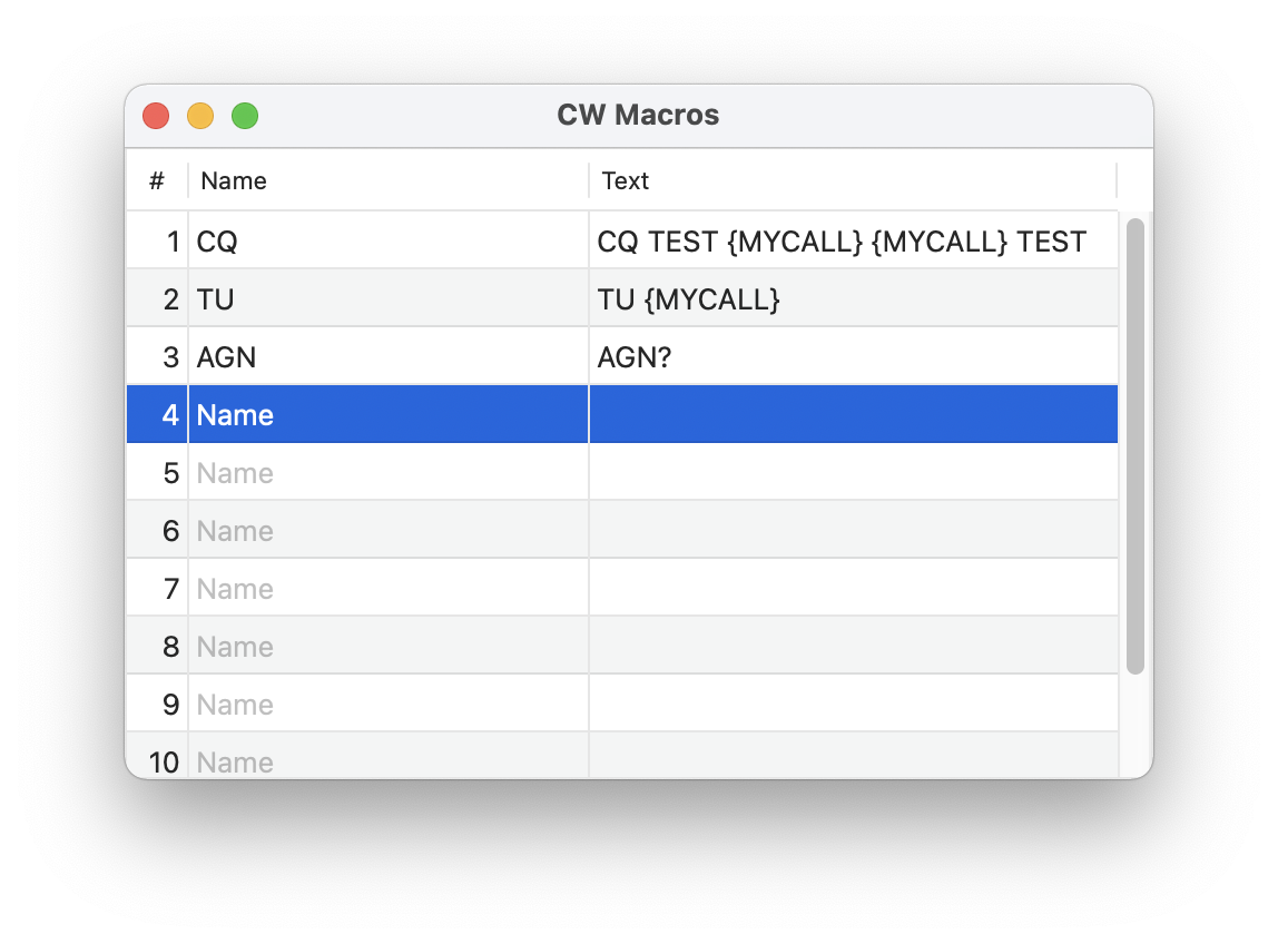
For easy access, the Macro Names will be used in the supplemental Macros view as follows:
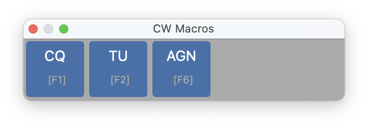
This view always displays the correct Macros for the corresponding mode.
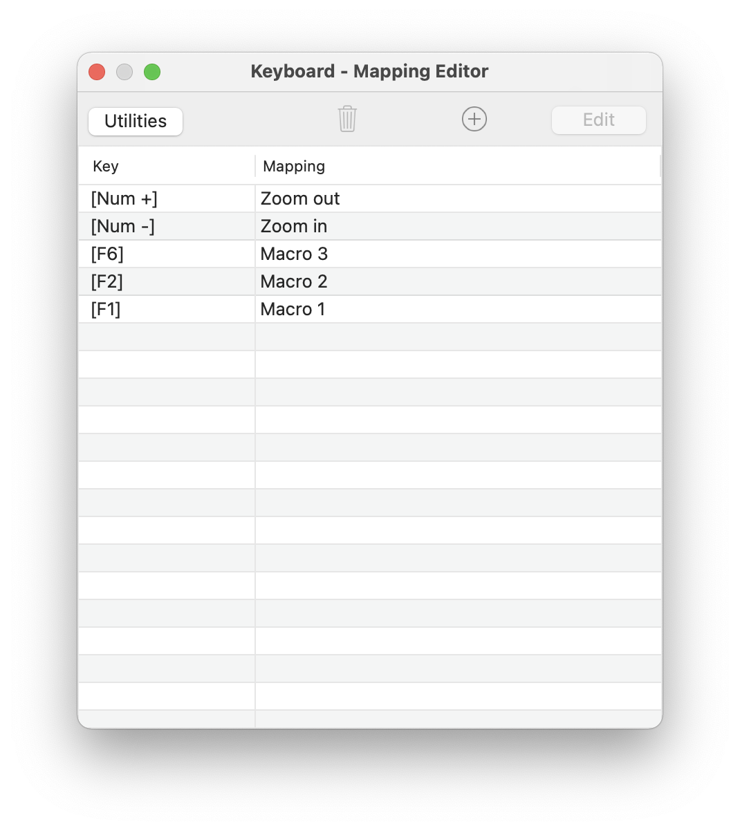
You can also assign keyboard keys for each Macro using the Tools → Keyboard menu:
Macros can use placeholder variables that will be replaced before sending. The available placeholder variables are listed in the attachment of this manual.
The assignment of RTTY or PSK Macros is similar to CW Macros. For Voice Macros you can record a message using the internal or attached Mac microphone.
For CW Macros, you can send pro-signs like BK by using the ^ prefix character (e.g. ^BK).
11. Advanced
11.1. Satellite Mode / Transverter
If you are using a Transverter or are operating Satellites, you may want to show the effective frequency in the App and even use the effective frequency for logging.
For this, you can maintain a frequency Offset under Radio Settings of the App. Here, you can set and adjust the Offset frequency independently for RX (Receive) and TX (Transmit). The translated display frequency will be shown below for your reference.
Remember, the TX frequency is always derived from the VFO displaying the red TX indicator. The indicator may change if you switch to Split, Dual-Watch or SAT Mode.
11.2. SAT Mode
The IC-9700 offers a SAT mode which is supported by this App. Activating SAT mode will result in the following changes:
TR (Tracking) mode will be enabled
DW (Dual Watch) will be enabled
TX will change from the left to the right VFO
When TR (Tracking) mode is enabled, the TX frequency will automatically adjust in response to any changes made to the RX frequency.
Note
The App does not yet support automatically doppler-shift adjustment.
To adjust the Offset between RX and TX frequencies, first turn off TR mode, then adjust the RX frequency (which is now independent of the TX frequency), and finally, re-enable the TR mode.
Once everything has been setup, your Waterfall screen may look like this:
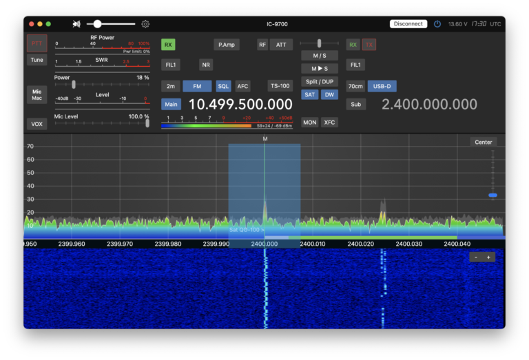
Both RX and TX VFO show the right frequency used for the Satellite. Moreover the band and mode indicators for the QO100 Satellite is available.
11.3. Switching the Radio on or off
A radio cannot be completely shut down by an App. It can only be put in standby mode or woken up from standby. To put the radio in standby mode, you can use the Power icon right of the Connect/Disconnect button. You can also configure a setting in the Settings menu to make the radio go into standby whenever you disconnect from it.
If you turn off the radio using the power button, you won’t be able to turn it on again with the app. To prevent this from happening and to bring the Radio into Standby mode instead of turning it off completely, you can configure a corresponding setting as follows:
For the IC-705:
Menu → Set → Function → Power Off Setting (for Remote Control) → Standby/Shutdown
or for other Radios:
Menu → Set → Network → Power Off Setting (for Remote Control) → Standby/Shutdown
Once this setting is configured, the radio will ask whether to power it off or put it in standby mode whenever you use the power button.
1. Tools
Within the Tools menu, you’ll discover a variety of useful functionalities that enhance the capabilities of this App.
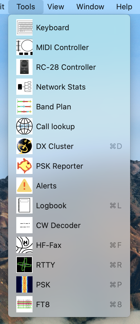
Tools such as the Network Stats Tool serve informational and debugging purposes. Others, like the Controller Tools, provide additional control features for the App. The Logbook tool can be utilized independently, even when not connected to the radio; however, all tools are fully integrated and operate seamlessly with both the App and your radio.
2. Keyboard Key Assignment
It is possible to assign Keyboard keys to Radio and App functions in the same way as it is possible to assign functions for MIDI controllers (see next chapters).
This feature allows you to not only map keys for Push-to-Talk (PTT) or CW keying but also for changing Bands, activating Auto-tune, launching the FT8 Tool, adjusting Frequency, and many other operations.
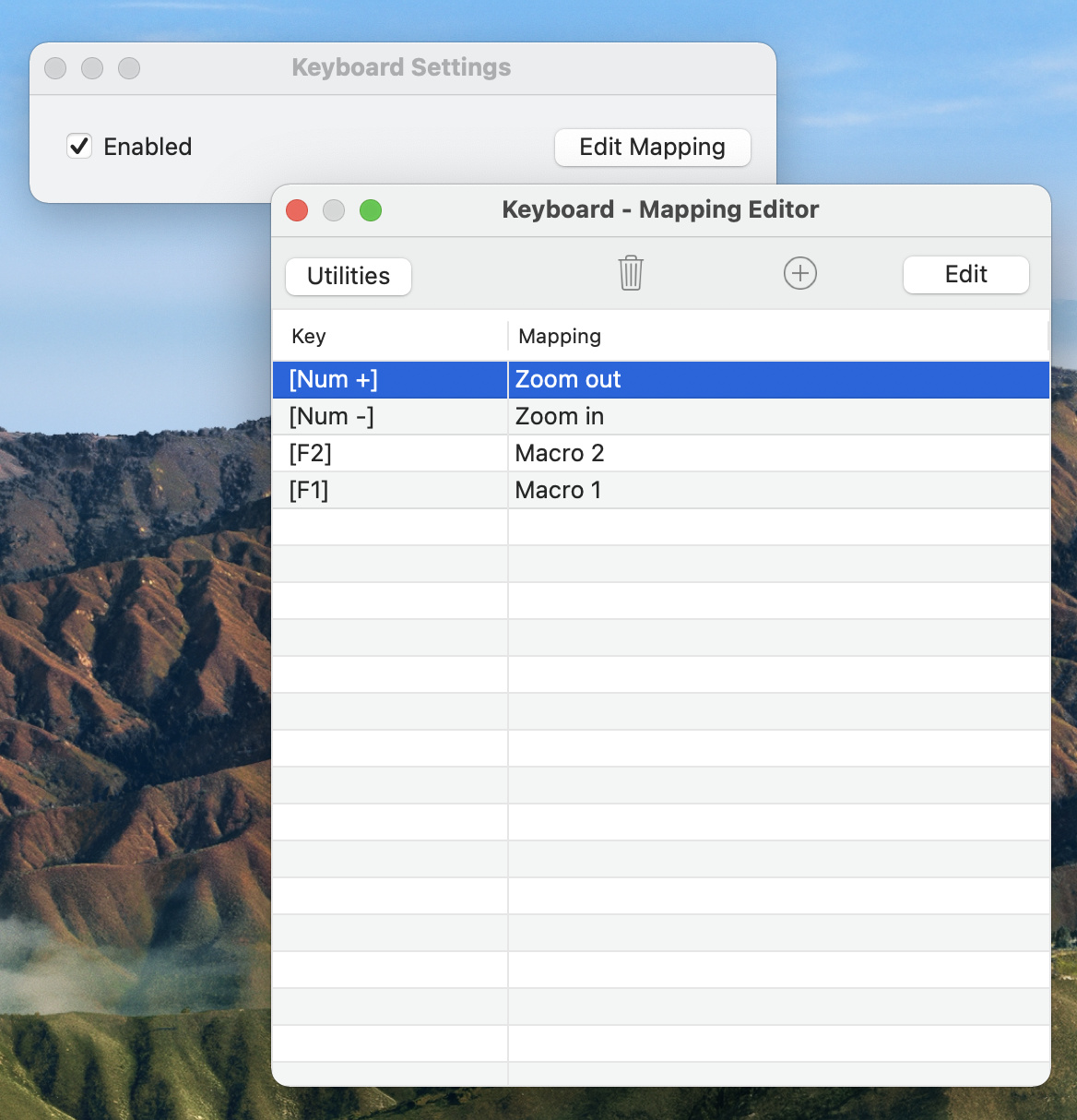
Within this section, you can enable or disable Keyboard assignments. To map keys to specific functions, click the Edit Mapping button to open the Keyboard Mapping Editor.
Use the Keyboard Mapping Editor to link individual Keyboard keys with specific Radio or App functions.
To add a new Keyboard assignment, click on the + icon at the top of the window.
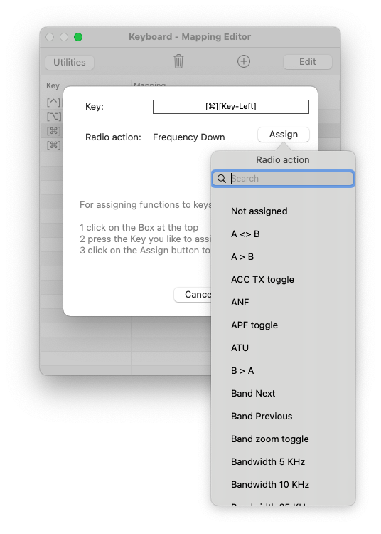
To map a new key, click on the square field next to the “Key:” label.
Press the desired key on your Keyboard that you want to assign a function to. Modifier keys such as Shift, Control, Option, and Command can be used in combination with a Letter, Number, or Function Key.
Note
Some keys may not be assignable due to existing System or App defaults. An appropriate message will be displayed in such cases. Additionally, assigning common keys like letters, numbers, or arrows could interfere with data entry within the App’s text fields. To avoid this issue, it is recommended to use these keys in combination with modifiers like Control, Option, or Command.
Finally, click on the Assign button to select the desired Function.
3. RC-28 Controller
Under Tools → RC-28 Controller, you can configure your Icom RC-28 Controller, if available.
Once your RC-28 Controller is connected to your Mac via USB cable, you will be able to select your Controller as “Icom RC-28 REMOTE ENCODER” in the Device selection.
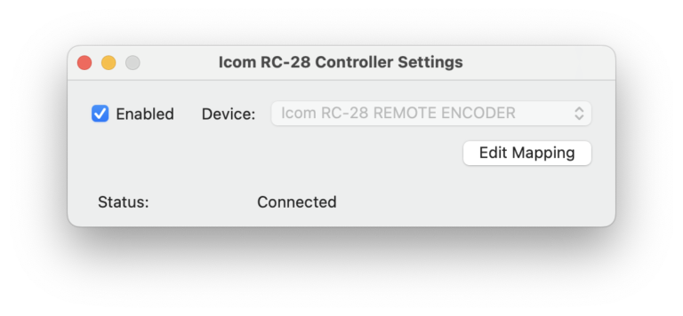
After selecting this device and checking the Enabled checkbox the Status should change to Connected. Should that not be the case, un-check “Enabled”, reconnect the cable and try again.
Once the device is connected, you can maintain button and wheel assignments of the RC-28 controller by hitting the “Edit Mapping” button.
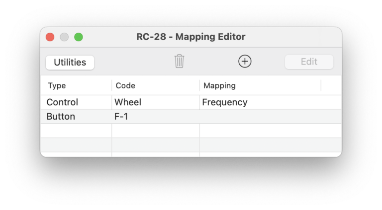
From inside this Mapping Editor, you can push the buttons or spin the control wheel and will see the corresponding entry appearing or highlighting in the list.
Next, click on “Edit” to assign a function to the selected control.
4. MIDI Controller
Under Tools → MIDI Controller, you can configure so called MIDI Controllers such as the DJ2GO2 or “Behringer CMD Micro MIDI Controller” for use with the Radio.
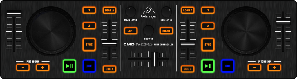
The following MIDI Controllers are supported:
Numark DJ2GO2
Behringer CMD Micro
Behringer CMD PL-1
Hercules DJ Controller Compact
Other controllers may work as well but they are not tested.
The MIDI Controller needs to be connected to your Mac using a USB Cable.
Once connected, you can assign functions to Keys, Knobs and LEDs by using the Midi Controller Tool.
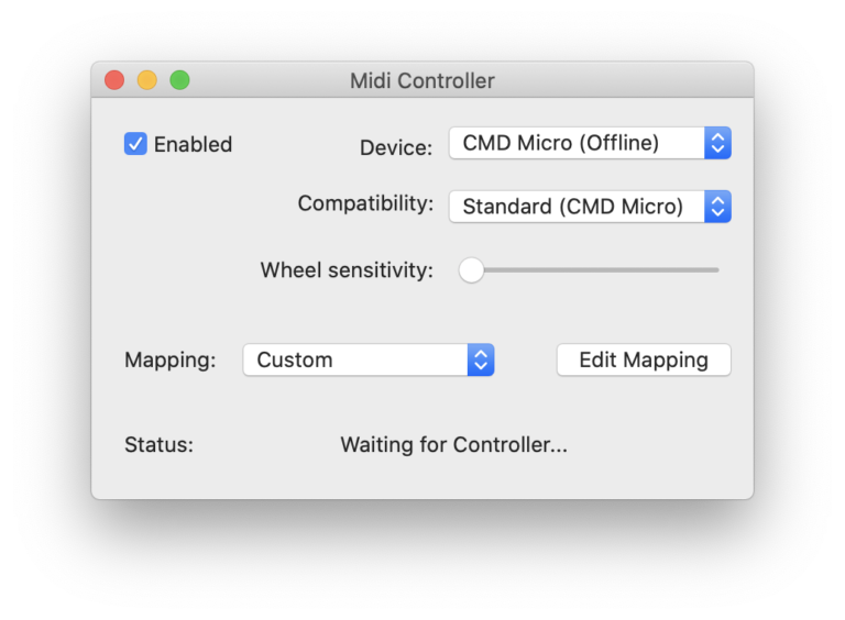
Use the Device selection to select the MIDI Controller you would like to use. Select the type of Controller using the Compatibility selection. If the list doesn’t contain the type of controller you are using, try the different types and see which one works best.
You can use the Standard / Default CMD Micro Key mapping or you assign your own keys by clicking “Edit Mapping”.
Ensure that you have checked the “Enabled” checkbox and the Status shows “Connected” before editing your mapping.
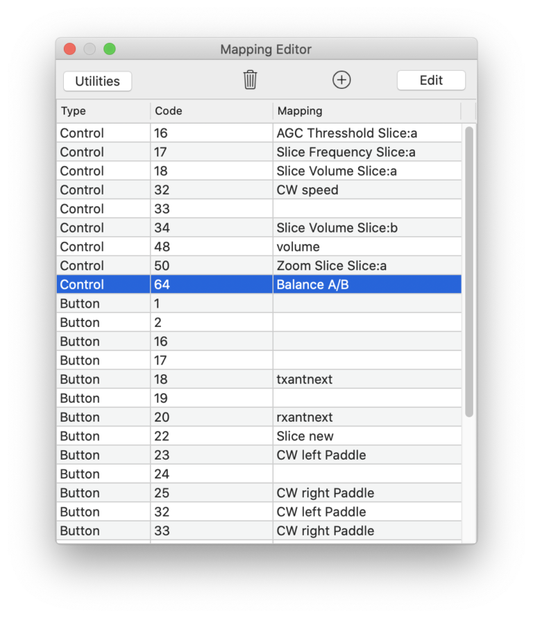
You can assign Functions on Buttons, Controls (or Wheels and Sliders) and LEDs.
For assigning functions to Buttons or Controls, just hit the corresponding Button or turn the knob or slider on your Midi controller. A line with the corresponding code of the Control will be added, if necessary and highlighted.
Now, double-click this line or click Edit.
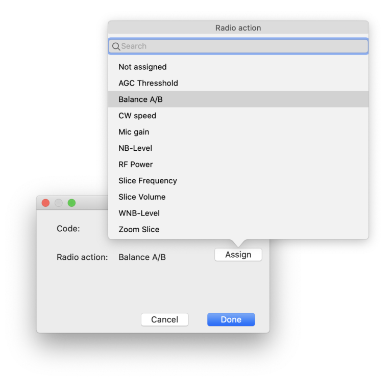
Next, click on “Assign” to get a list of possible assignments. There are different assignments for Buttons and Controls. Buttons can trigger or toggle a setting whereas Controls can change values.
Select the desired Transceiver action and click on done.
LEDs need to be added in a slightly different way. First click on the (+) Icon at the top and select LED.
Now, you either need to enter the code for the LED on your MIDI Controller manually or you can try to hit a button which has an LED included. For some controllers, the code for the LED is identical to the code for the button but that’s not the case for all Controllers so you might have to experiment with different code numbers or get the codes from the manual. Once a code has been entered, you can hit Test so see if the desired LED turns on and off. Finally, you can click on Assign to decide when the LED should be turned on by the Radio.
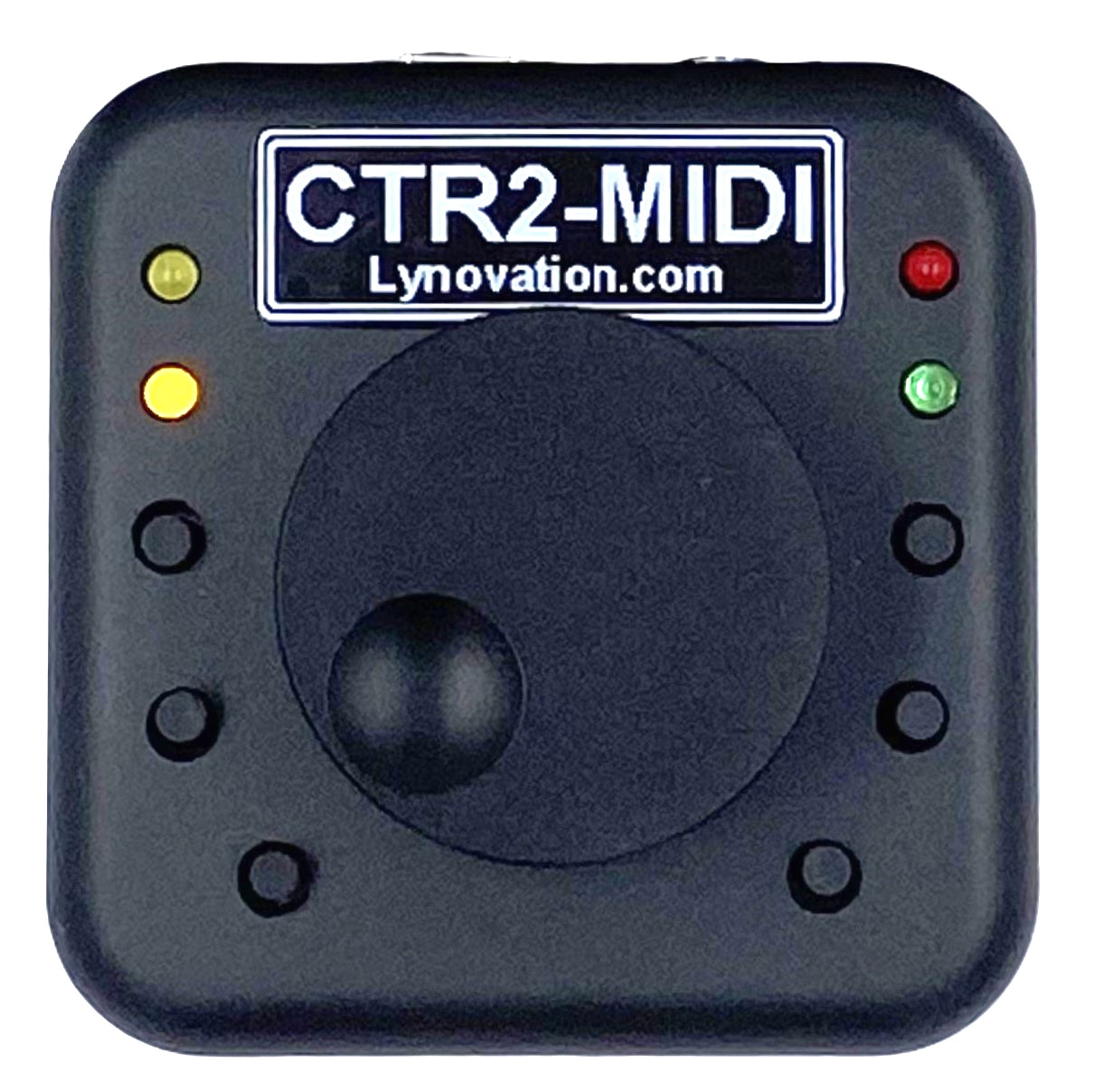
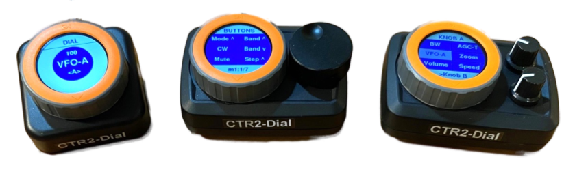
5. CTR2 Controller and CTR2 Dial Controller
These two tools enable the use of the CTR2-MIDI and CTR2-Dial Controllers, which are available for purchase from Lynn Hansen, KU7Q at https://ctr2.lynovation.com.
These Controllers serve as an interface for the radio, allowing operators to tune frequencies, adjust volume, activate PTT, and access several other features.
Additionally, they provide the capability to connect a CW paddle to your device.
The CTR2-Controllers offer the flexibility of wireless connectivity via Bluetooth-LE or a wired connection through a USB adapter.
To pair a CTR2-Controller with your device via Bluetooth, ensure that the controller is powered on and in proximity to your device. Then, launch the CTR2 Controller or CTR2-Dial tool and click the “Find Bluetooth-LE Device” button at the top. The CTR2 should be detected within a few seconds and appear in the Device list. If the initial attempt is unsuccessful, close the tool, reopen it, and try again. Once the controller is detected, you can select it from the Device list under the name CTR2_xxxx whereas xxxx is a unique identifier different for each controller.
If you are connecting the CTR2 via USB, it will be listed as XIAO_ESP32S3 for the CR2-MIDI or STAMP-S3 for the CTR2-Dial Controller in the Device list.
After selecting the appropriate device and toggling the Enabled switch on, the status should update to Connected.
The controller comes with default mappings that allow you to use the knob for tuning, volume adjustment, and more. You can view and modify these mappings to suit your specific needs by clicking the Edit Mapping button.
Should you wish to revert to the default mappings after making changes in the Mapping editor, simply delete all mappings, close the editor, and reopen it.
When a paddle is connected to the CTR2, it is ready for immediate CW operation. You can operate in CW as usual by using the CW Mode Tool where you can also change CW Speed, Pitch, Side-Tone, Swap Paddles etc.
For additional information and a comprehensive manual, please visit Lynn’s website. Lynn has also predefined mappings available for the different Controller variants
6. Command Bar
The Command Bar feature is designed to maintain buttons that can be displayed on the Waterfall Main Screen. These buttons can open websites, start other apps, or send CAT commands to the radio. It is also possible to assign keyboard shortcuts to these commands.
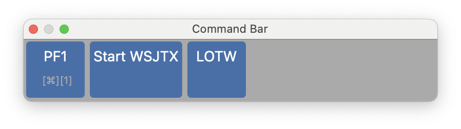
The feature consists of two parts: the screen where you maintain the buttons.
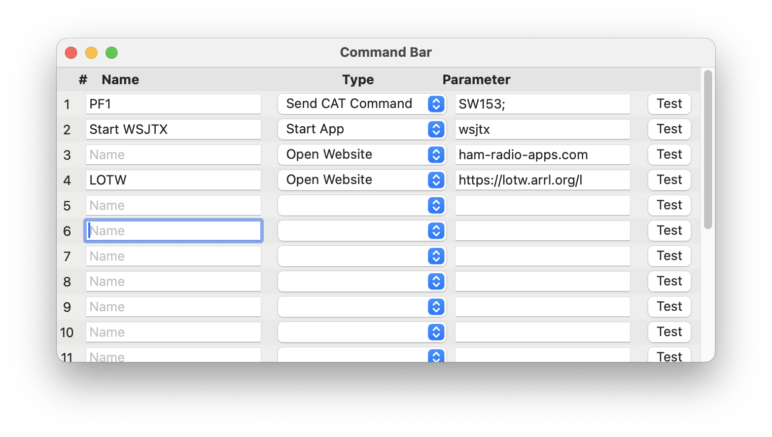
And the screen where the buttons are displayed.
To maintain a button, you can enter a Title, select a Type such as Start App, Open Website, or Send CAT Command. Depending on the type, you must enter a parameter which represents the app name, the website URL, or the CAT command.
The Title will be displayed on the Command Bar when shown on the Waterfall. You can leave the Title blank, in which case the button will not appear on the Command Bar, although it’s still possible to assign a keyboard shortcut to it.
To start apps, you need to enter the app name exactly as it appears in the Applications folder on your Mac, including spaces and case sensitivity. You can start multiple apps by separating app names with a ‘|’ character.
The commands to enter for the Send CAT Command type depend on the radio you are using. Please refer to the radio’s programmer’s reference documentation to learn which commands can be used.
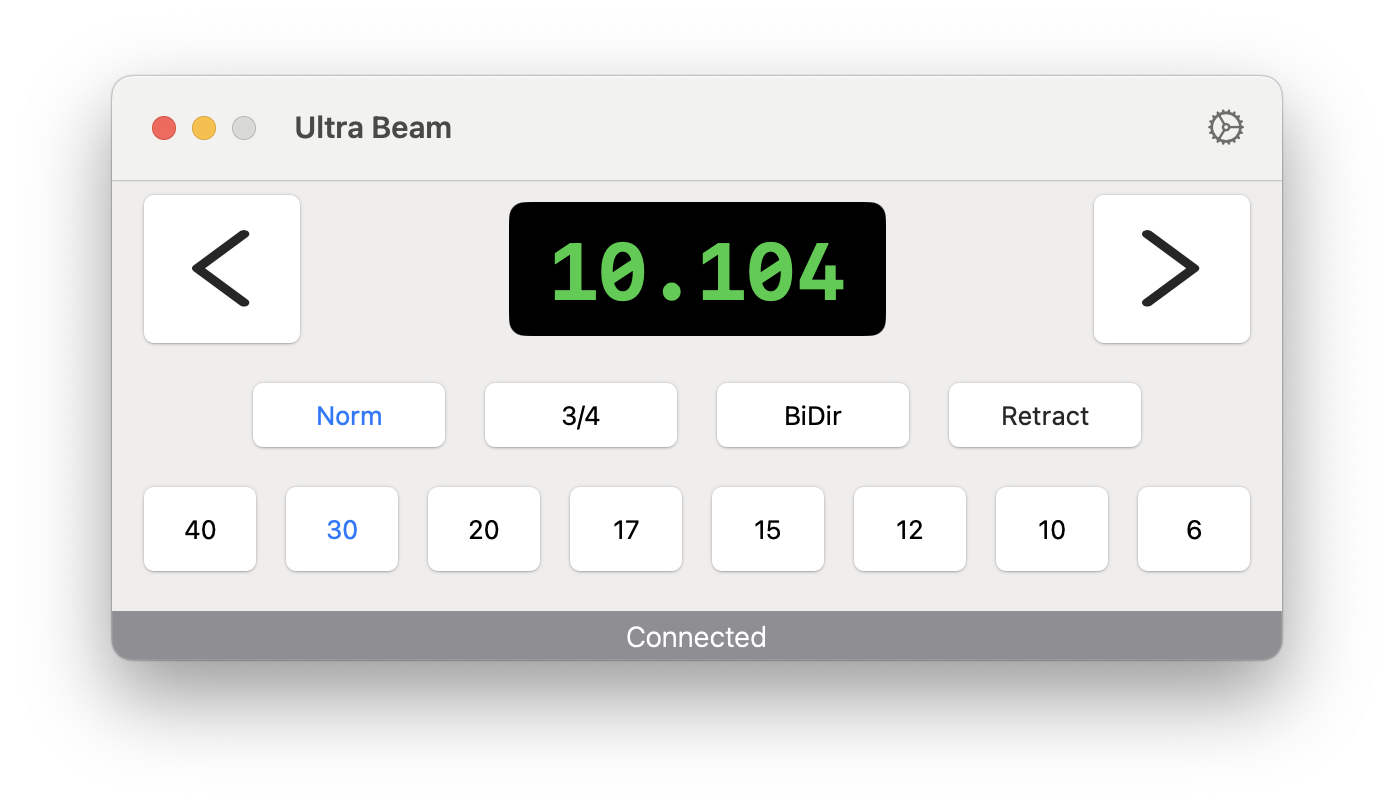
7. Ultra Beam
This feature is designed to control Ultra Beam Antennas. For more information on the different models and specifications, visit WiMo’s Ultra Beam page https://go-to.me/ultrabeam.
The Ultra Beam is often regarded as a more robust and dependable European alternative to the Stepp-IR.
7.1. Requirements
To utilize this feature, you need an Ultra Beam RCU-06 Control Unit and the UltraBeam Remote Controller software installed on a Raspberry Pi.
To set up this tool, hit the settings icon at the top of the interface.
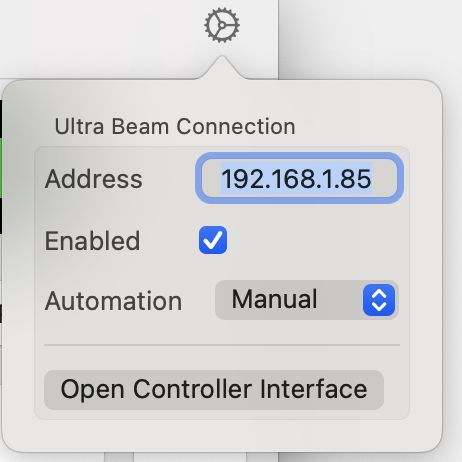
Here, input the IP address of your UltraBeam Remote Controller (the Raspberry Pi).
To test the IP Address, click the Open Controller Interface button to access the Controller’s web interface.
The ‘Automation’ section offers three options: ‘Manual’ allows you to control the frequency of your Ultra Beam directly from the main Tool screen. ‘Follow RX’ or ‘Follow TX’ will automatically adjust the frequency based on the current RX or TX frequency, respectively.
To control the frequency on the main Tool screen, simply hit one of the Band buttons or hit the frequency display at the center to manually enter a frequency. You can also adjust the frequency in 5 kHz increments by hitting the buttons to the left and right of the frequency display.
You can also remote-access your Ultra Beam over the internet. To do this, open port 80 on your router for the IP address of your Ultra Beam Controller. It is recommended to use a different port than 80 externally, for example, 20001. In this tool, you would then need to enter your public IP address (or a DynDNS name - see the chapter Remote Access for more details) followed by a colon and the port number (20001 in the example).
Note
No CAT cable or CAT connection to the Ultra Beam Controller is required for this tool to function. You can switch radios and still be able to adjust the frequency for the radio you are currently connected to.
For further details, please refer to the Ultra Beam manuals.
8. Metropwr
This tool supports Metropwr devices such as the FX755 MK2 Power Meter, the FX 7 Antenna Switch, and the RT1 Antenna Rotor Controller.
For product details, visit: https://www.metropwr.com
8.1. Prerequisites
Before using the tool, install and configure the Metropwr devices as described in their manuals. Each device must be connected to the local network with a LAN cable.
The only exception is the FX 7 Antenna Switch. It does not connect to the network directly but to an FX755 MK2. One FX755 MK2 can control up to two FX 7 Antenna Switches, connected in series.
8.2. Adding Devices
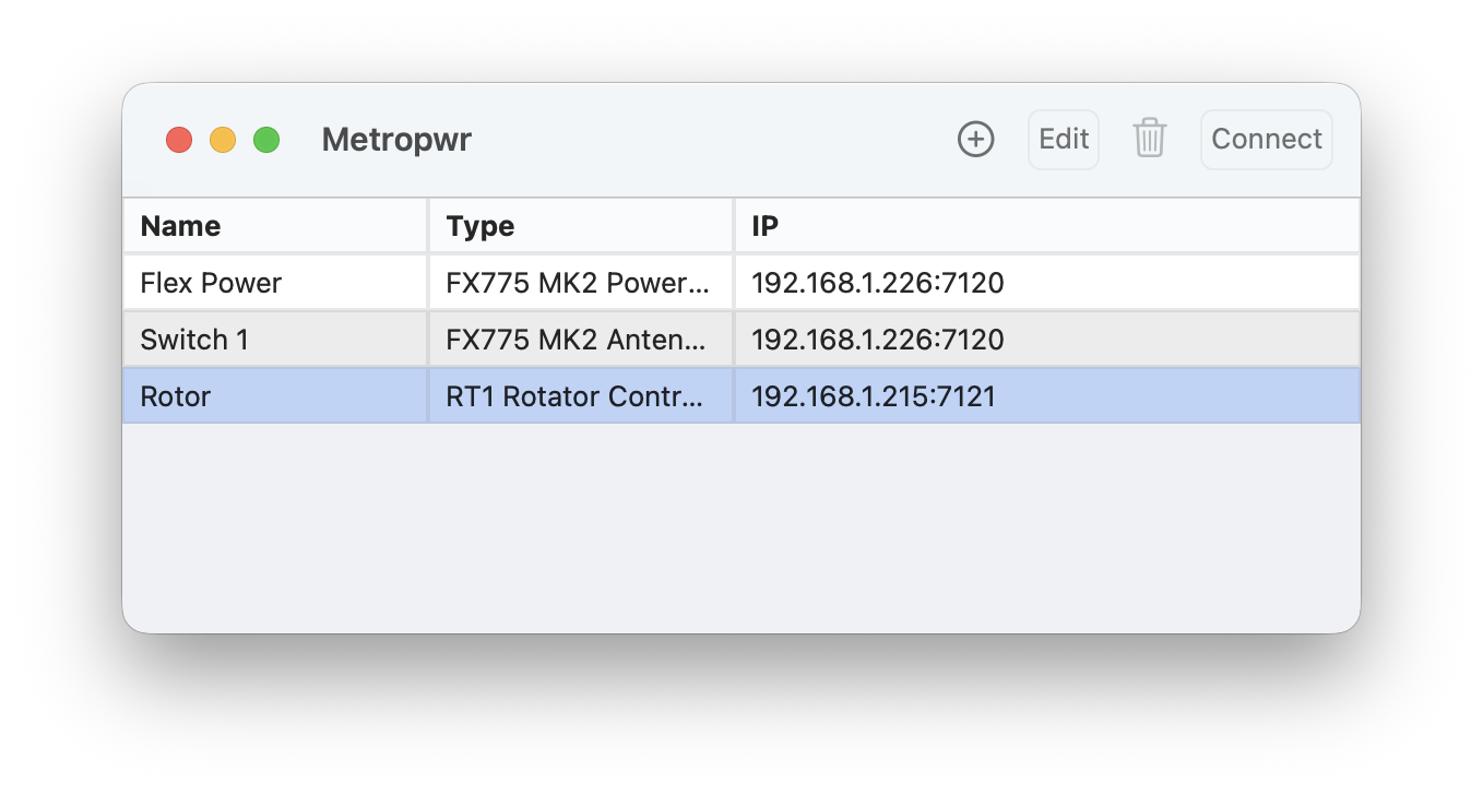
Open the Metropwr tool and press the plus button at the top to add a device. Select the type of device you want to add: FX755 MK2 Power Meter, FX 7 Antenna Switch, or RT1 Rotator Controller. Then enter the IP address of the device.
Note
For the Antenna Switch, enter the IP address of the FX755 MK2 to which it is connected.
The port number is filled in automatically. It is 7120 for the FX755 (Power Meter and Antenna Switch) and 7121 for the RT1.
If you enable Auto open, the device screen will appear automatically when the app starts.
Otherwise, you can open a device screen by selecting it in the list and clicking Connect or by double-clicking the entry.
Some devices have additional settings that can be adjusted as explained below.
Using the Edit or Trash Icon you can maintain the settings or remove a device from the list.
8.3. FX755 MK2 Power Meter
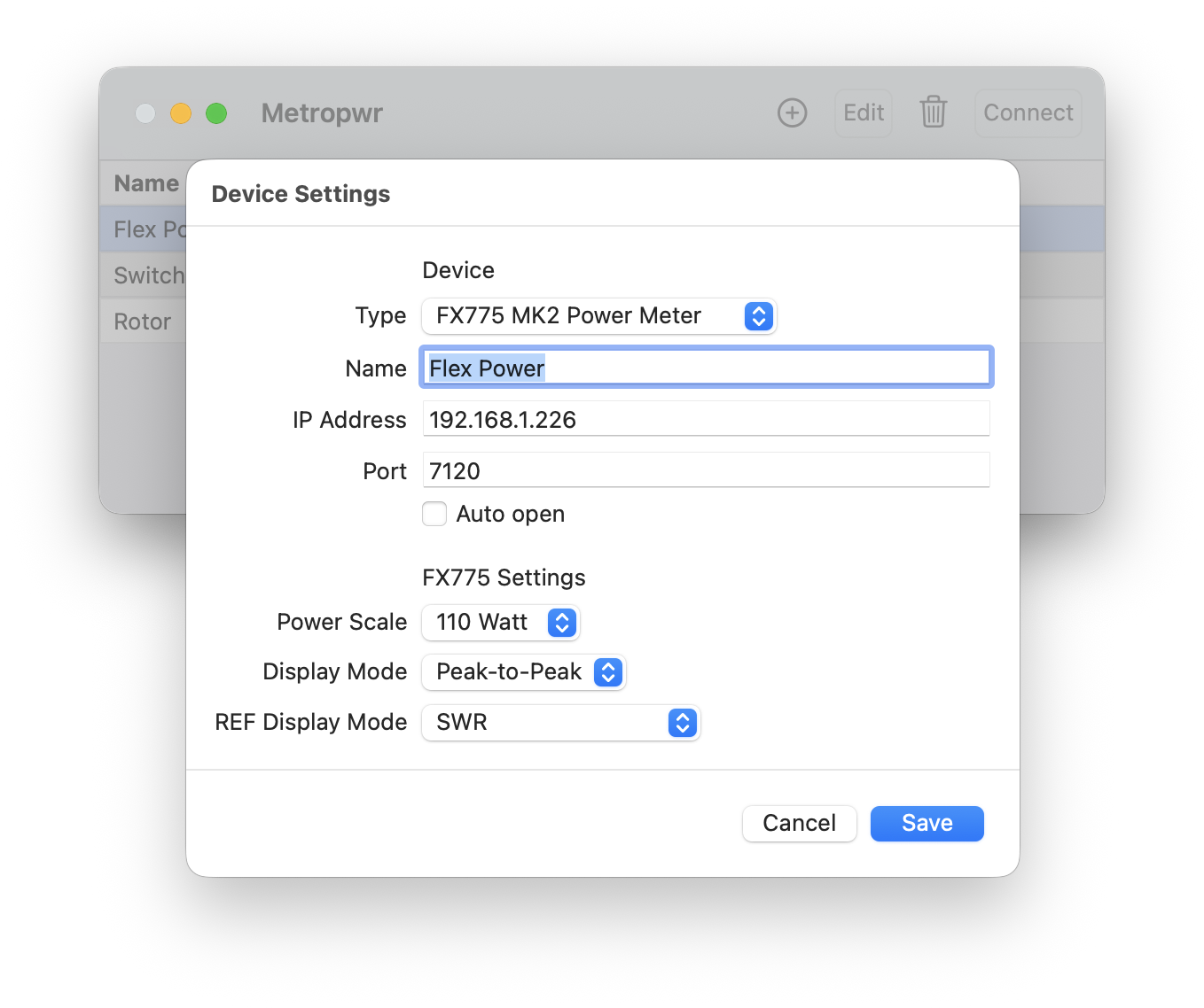
In the settings you can select the power scale (10 W to 6 kW), the display mode (Peak-to-Peak or Average), and the numerical display (SWR, dBm, or Reflected Power). These options can also be changed from the Power Meter screen, but they will revert on the next start to the settings you define here.
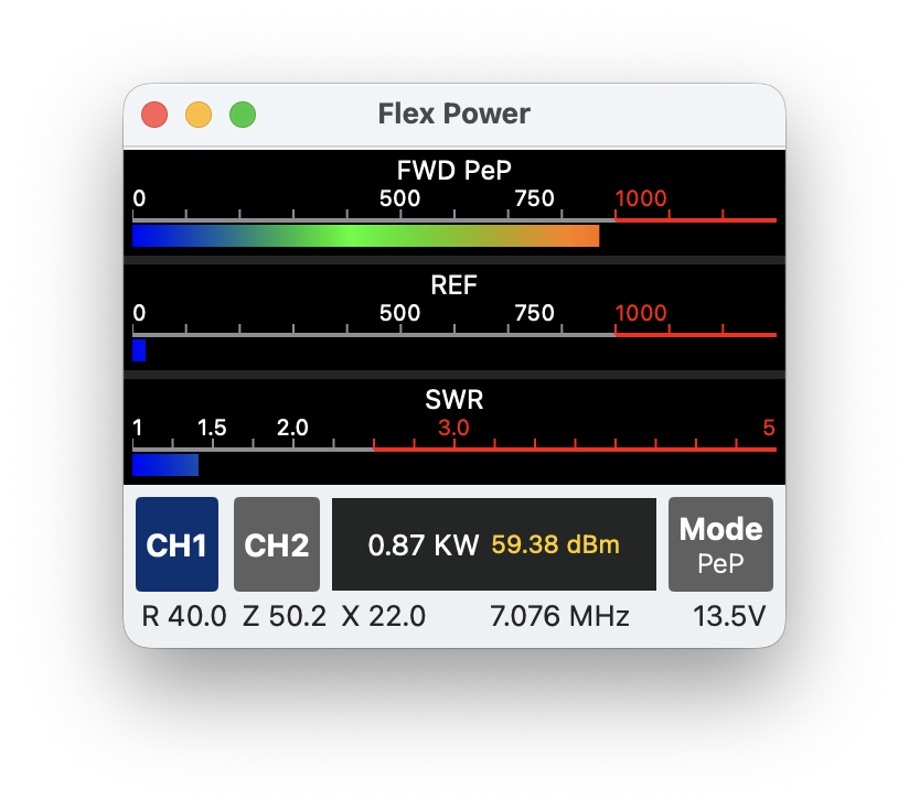
The Power Meter screen shows three meters: power (PeP or Average), reflected power, and SWR. With the CH1 and CH2 buttons you can switch between the two channels of the FX755 MK2. The Mode button toggles between Peak-to-Peak and Average. Hitting the power scale cycles through all ranges from 10 W up to 6 kW. Hitting the numerical display cycles between SWR, dBm, and Reflected Power.
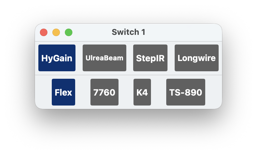
8.4. FX 7 Antenna Switch
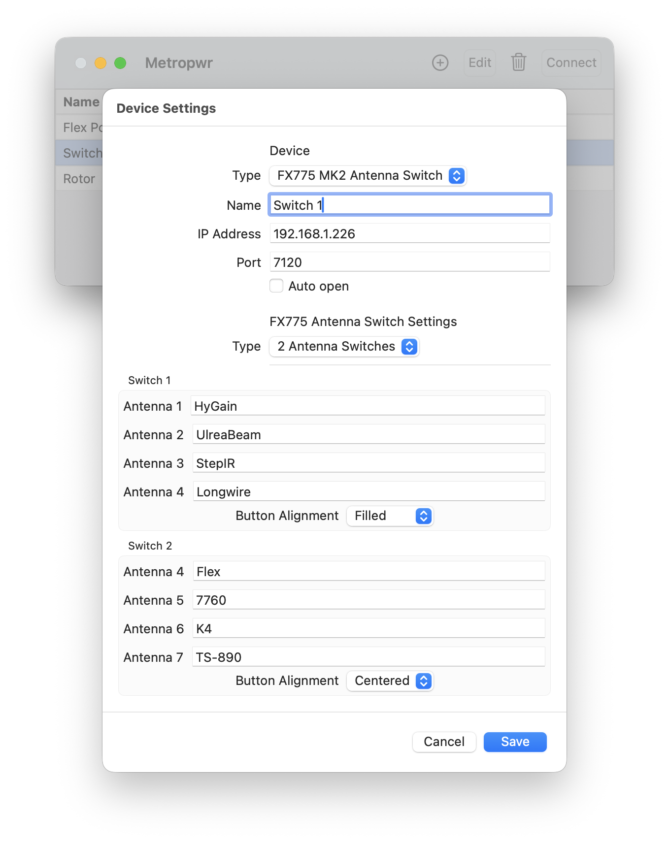
In the settings you can define whether you use one or two antenna switches. You can also assign labels to each antenna button and choose how the buttons should be aligned on the device screen.
8.5. RT1 Rotator Controller
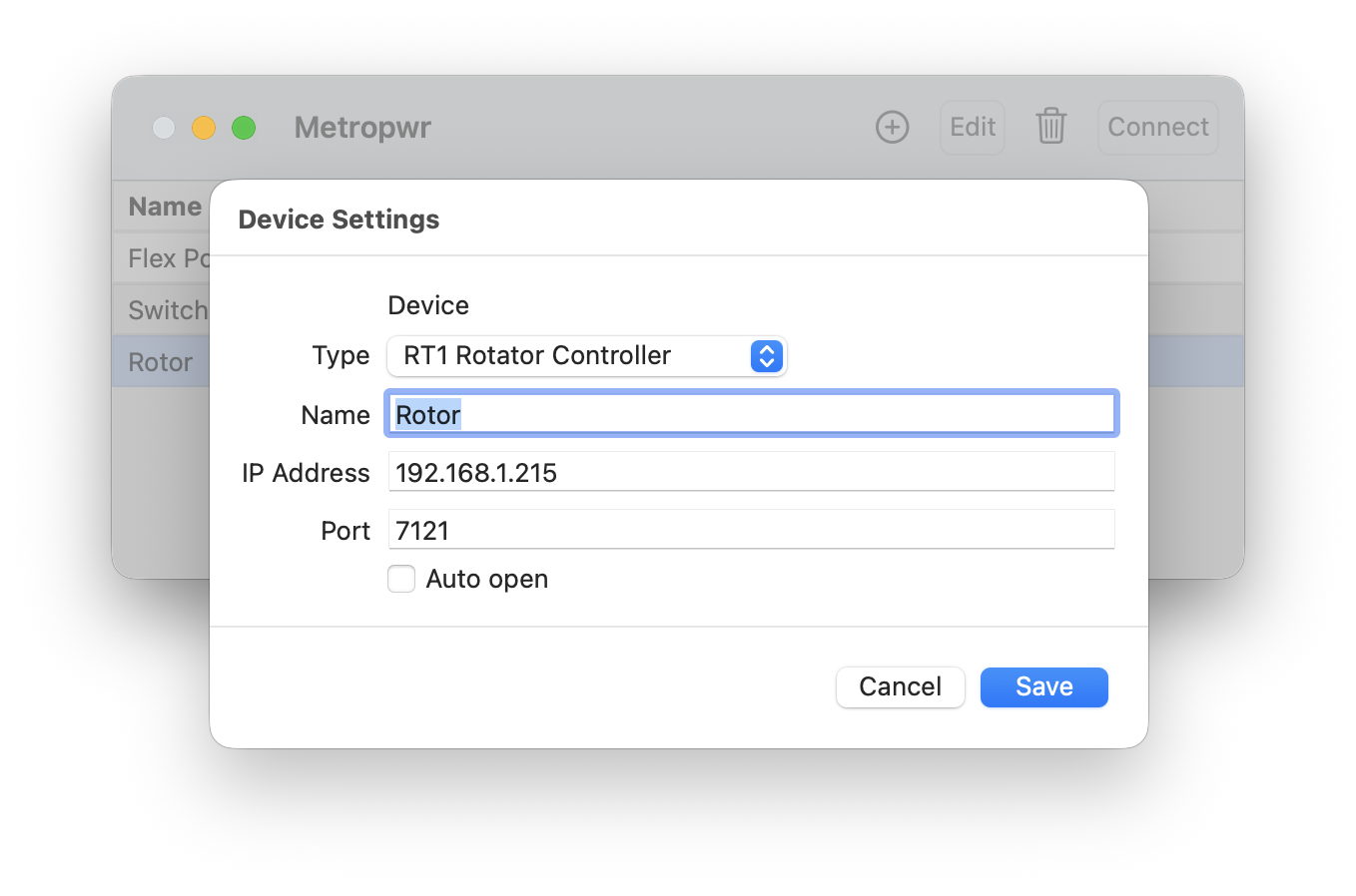
The RT1 Controller has no additional settings.
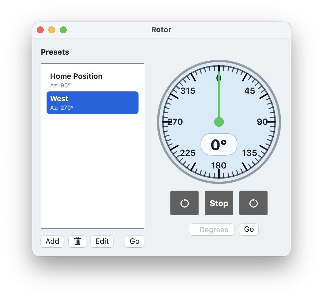
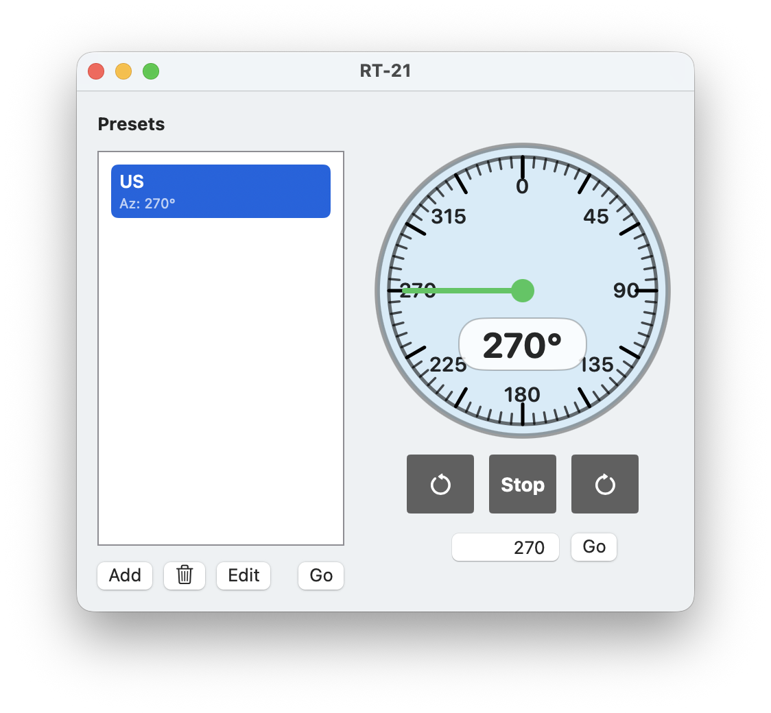
The device screen includes a preset list where you can store and recall common positions such as “Home.” Use the buttons to add, edit, or delete presets. Press Go or double-click a preset to move to that position.
The blue compass shows the current direction. The CCW and CW buttons turn the rotator counter-clockwise or clockwise. The Stop button halts rotation immediately. You can also enter a degree value directly and press Go to move the rotor to that heading.
Note
This interface allows you to control the rotator directly. Additionally, you can automatically position your antenna to align with another station’s location using the Call-Lookup tool or the app’s maps. For more details on these features, refer to the Rotator Integration section later in this manual, found under Attachments.
8.6. Remote Access
For remote access, the corresponding ports must be opened in your router: 7120 for the FX755 (Power Meter and Antenna Switch) and 7121 for the RT1.
When accessing from outside your local network, you need to use your public IP address or a DynDNS name instead of the local IP. If you are using a VPN connection to your local network, you can use the same IP and ports as if you were at home.
9. Green Heron
This tool supports the Green Heron RT-21 Antenna Rotor Controller.
For product details, visit: https://www.greenheronengineering.com
9.1. Prerequisites
This tool requires an Green Heron RT-21 rotator controller equipped with a LAN or WiFi option.
Before using the tool, install and configure the RT-21 as described in the manufacturer manual.
9.2. Adding Devices
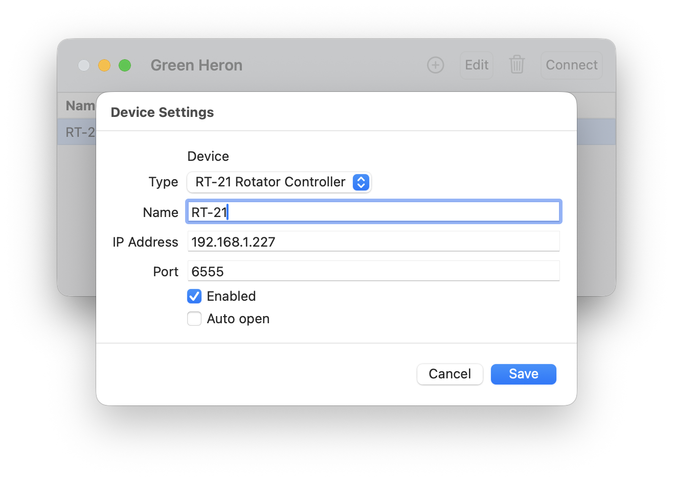
Open the Green Heron tool and press the plus button at the top to add a device. Enter a name and the IP address of the RT-21. If you have not changed the port number in the RT-21 Setup tool, the default port number is 6555.
If you enable Auto open, the device Rotator screen will appear automatically when the app starts.
Otherwise, you can open a device screen by selecting it in the list and clicking Connect or by double-clicking the entry.
Using the Edit or Trash Icon you can maintain the settings or remove a device from the list.
9.3. RT-21 Rotator Controller
The RT-21 device screen includes a preset list where you can store and recall common positions such as “Home.” Use the buttons to add, edit, or delete presets. Press Go or double-click a preset to move to that position.
The blue compass shows the current direction. The CCW and CW buttons turn the rotator counter-clockwise or clockwise. The Stop button halts rotation immediately. You can also enter a degree value directly and press Go to move the rotor to that heading.
Note
This interface allows you to control the rotator directly. Additionally, you can automatically position your antenna to align with another station’s location using the Call-Lookup tool or the app’s maps. For more details on these features, refer to the Rotator Integration section later in this manual, found under Attachments.
9.4. Remote Access
For remote access, the port 6555 must be opened in your router.
When accessing from outside your local network, you need to use your public IP address or a DynDNS name instead of the local IP. If you are using a VPN connection to your local network, you can use the same IP and ports as if you were at home.
10. Waveshare
This tool supports Waveshare devices such as the RS232 to ETH and Ethernet Relay devices.
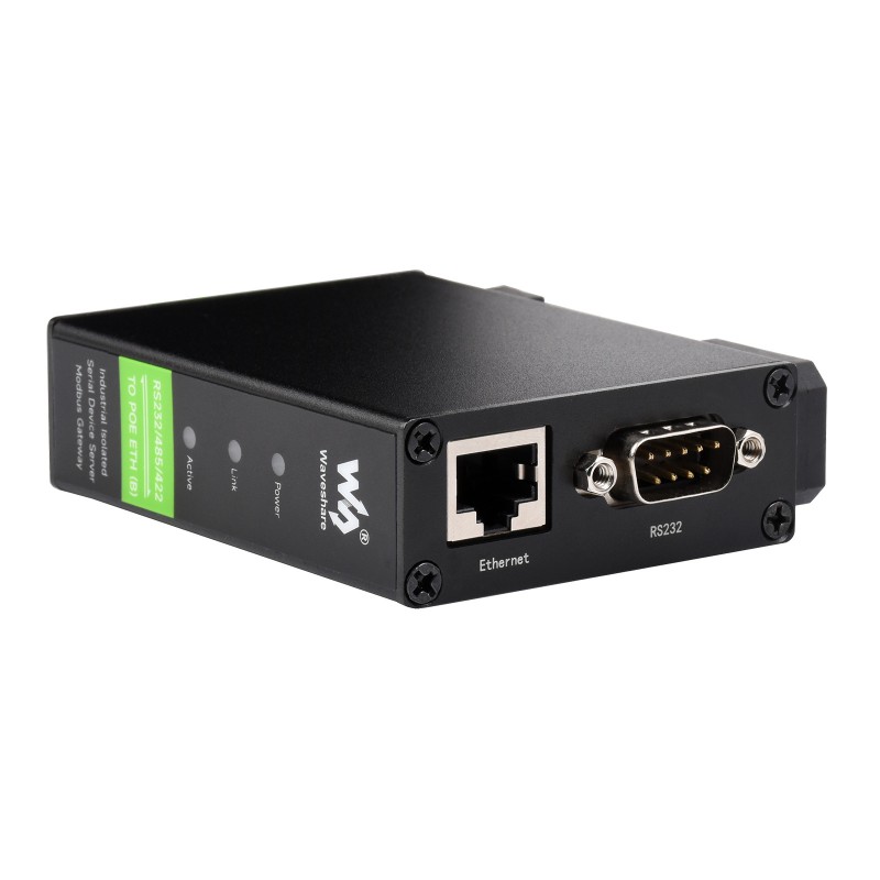
The RS232 to ETH device can be used to provide a remote CAT interface for antenna controllers like the Ultra Beam RCU-06, antenna tuners, power amplifiers (PAs), or any device that supports an RS232 (serial port) CAT interface.
Amazon links for the Waveshare RS232 Ethernet Adapter: https://amzn.to/49ILUN5 or as POE version https://amzn.to/4wo570o
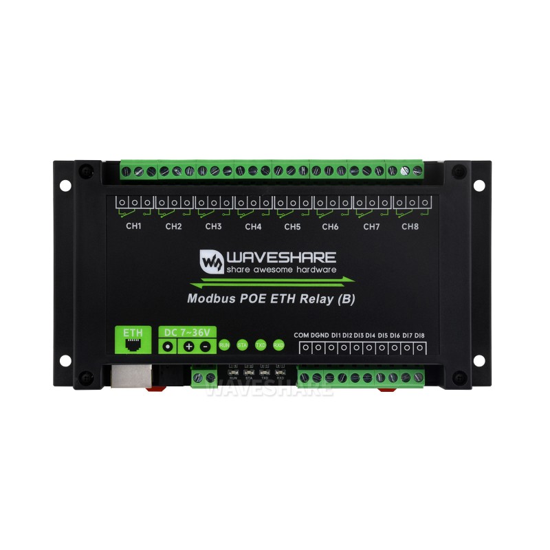
The Ethernet Relay device can be used to switch your radio or any other device using one of its eight relays. It also features eight input ports that can be used to trigger PTT (push-to-talk) or signal their status in the app.
Amazon link for the Waveshare 8 Port Relay Adapter: https://amzn.to/4dg1fWj
There are several variants of each device from Waveshare, all of which are supported. Some models have one or two Ethernet ports—the second port can be used to daisy-chain other devices. Variants with and without Power over Ethernet (PoE) are available. PoE devices can be powered via Ethernet or via a 7–36V power supply, like non-PoE models.
For more details, visit the official Waveshare product pages:
RS232 to ETH devices: https://www.waveshare.com/product/rs232-485-422-to-poe-eth-b.htm
Ethernet Relay devices: https://www.waveshare.com/modbus-poe-eth-relay-b.htm
These devices can be purchased directly from Waveshare, or through online retailers such as Amazon and eBay.
10.1. Prerequisites
Before using this tool, ensure your Waveshare devices are correctly installed and configured. Each device must be connected to your local network via LAN cable.
10.2. Setting up a Waveshare device
The setup process is the same for all device types.
Connect and Power Up: Connect the device to your local network using a LAN cable and power it on.
Access the Configuration Interface: Open a browser and navigate to the device’s IP address. By default, this is often x.x.x.254, where x.x.x matches the first three numbers of your local network (e.g., 192.168.1.254). If unsure of the IP address, check your router’s device list or consult the Waveshare website for instructions.
Login: When prompted for a password, simply click the login button (leave the password blank).
Adjust Configuration: You should see a page like the one below:
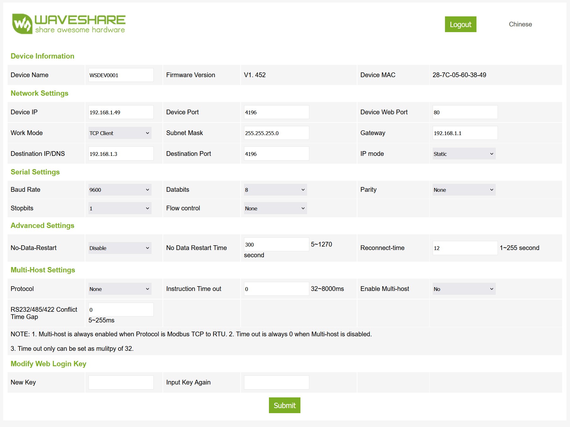
Modify or confirm the following settings:
Device IP: Set to a static IP address outside your DHCP range.
Work Mode: Set to TCP Client.
Device Port: Keep the default 4196 unless you plan to access the device over the internet. In that case, assign a unique port per device.
For RS232 to ETH devices:
Adjust Serial Settings according to the requirements of the device you are connecting to (e.g., 9600 Baud, appropriate stop bits and parity).
Apply Settings: Click Submit to apply the changes. The device will now be reachable via the assigned IP address.
Physical Connection (RS232): Connect the RS232 ETH device to your target device using a standard RS232 cable. Depending on the connector type, you may need a male-to-female or female-to-female cable. A crossover cable is usually not required.
Positioning (Relay): For Ethernet Relay devices, it may be helpful to place the device near your Apple device during setup to monitor the relay/input status via the blue indicator LEDs.
10.3. Adding Devices
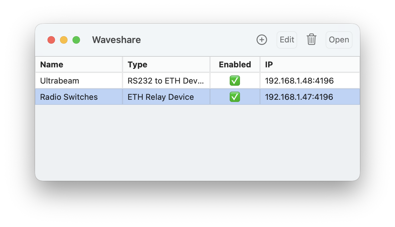
To add a device in the Waveshare tool of the app:
Open the Waveshare tool and click the plus (+) button.
Select the type of device you want to add.
Fill in the required information:
IP Address of the device.
Port (default is 4196, unless otherwise specified).
Enabled: Check to activate the device. Uncheck if it’s temporarily offline.
Auto Open: If enabled, the device’s screen will open automatically when the app starts.
To open a device screen manually, select it from the list and click Open, or simply double-click it. Use the Edit or Trash icons to modify or delete the device.
Some devices have additional settings that can be adjusted as explained below.
10.4. RS232 Ethernet device
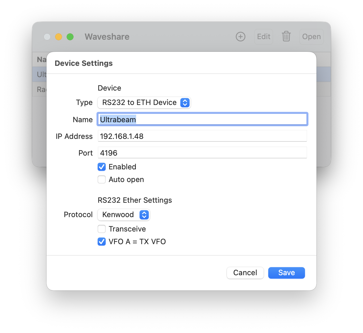
Configure the CAT interface settings:
Protocol: Choose based on the remote device’s protocol—Kenwood (common), Yaesu, FlexRadio, or Elecraft.
Transceive: Leave off if the destination device is polling the frequency. Enable if you want the app to send CAT commands when settings change.
VFO A = TX VFO: If enabled, the VFO A CAT command uses the current TX frequency. Otherwise, it uses RX. For tuners or antenna controllers, enabling this is recommended.
To open the device screen, double-click the device or click Open.
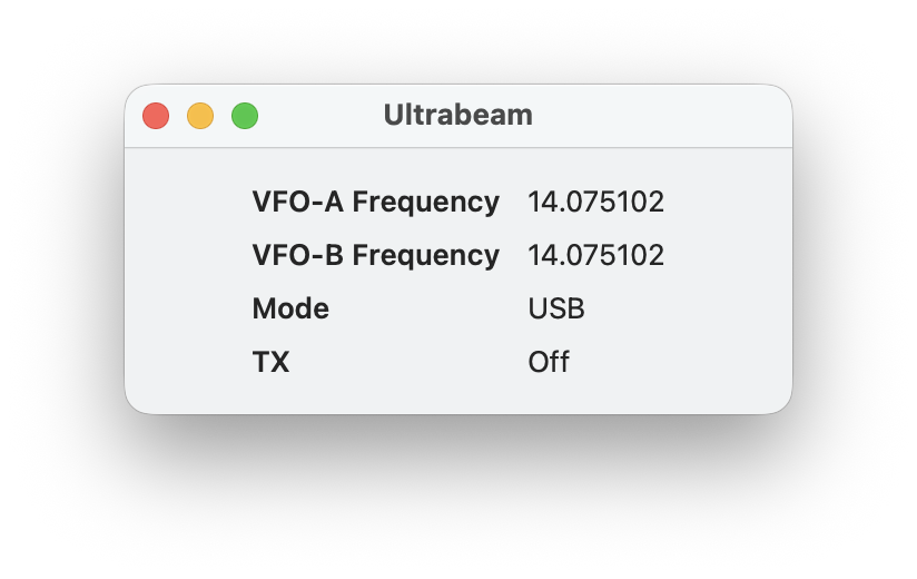
To display this screen, the Waveshare device must be working and you need to be connected to your Radio. This screen shows the information which is sent via CAT to the device.
Note
If you have an Ultra Beam RCU-06, you can still use the app’s built-in Ultra Beam tool. However, using a Waveshare device often provides a more reliable connection—at the cost of not being able to retract or change direction. You can also use both methods together.
10.5. Ethernet Relay device
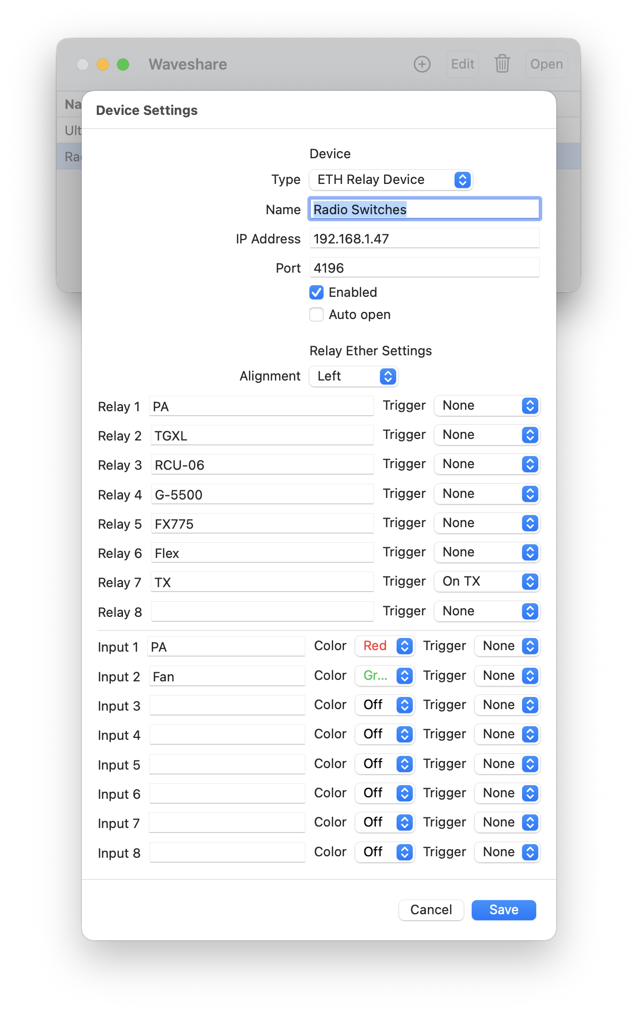
Configure relays and inputs:
Relay Titles and Triggers: Assign titles for each relay. Set triggers such as “on TX” or “on Connect” to activate a relay when transmission starts or when connected.
Input Names and Triggers: Assign names and colors to each input. Set triggers (e.g., “PTT”) to activate specific actions when an input is triggered.
To open the device screen, double-click the device or click Open.
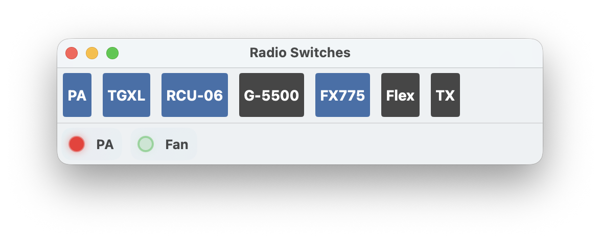
The on-screen button bar reflects the relay and input status. You can toggle relays directly from this interface.
10.6. Remote Access
For remote access, the corresponding port for each device must be opened in your router.
When accessing from outside your local network, you need to use your public IP address or a DynDNS name instead of the local IP. If you are using a VPN connection to your local network, you can use the same IP and ports as if you were at home.
11. S.A.T. Controller
This feature enables you to operate satellites using the S.A.T. Controller from CSN Technologies directly within the app.
For more information about this product, visit http://csntechnologies.net/sat
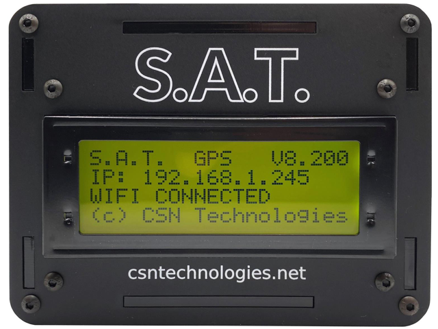
The S.A.T. device is a compact unit that connects to your antenna rotator for elevation and azimuth control, simplifying satellite operations. It features a network interface used by the app and an integrated web interface, eliminating the need for additional cables like a CAT cable.
11.1. Prerequisites / Requirements
Before using the S.A.T. tool, ensure you have:
A S.A.T. device
A compatible rotator, such as the G5500, connected to the S.A.T. device via a cable
The rotator should control your SAT antennas, which are connected to your radio
The S.A.T. device should be set up and operational as described in its user manual. You can skip the section about connecting a CAT cable to the radio, as this is managed by the app and this tool.
Once these prerequisites are met, launch the S.A.T. tool in the app and tap the gear icon to access the settings. Here, you will need to enter the IP address of the S.A.T. device, displayed on its small screen.
Next, press the Enable button. It may take a few seconds for the message “no SAT selected” to appear in the lower status bar of the tool. If the connection fails, perhaps due to an incorrect IP address, an error message will display instead.
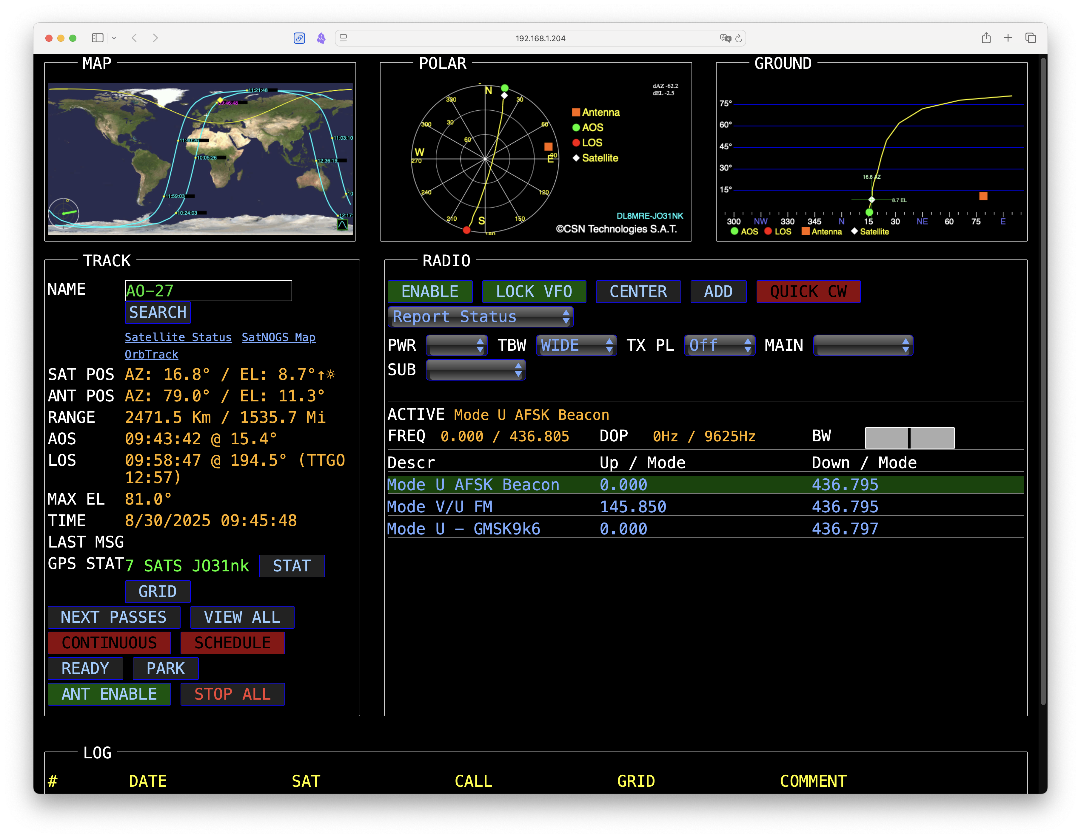
11.2. Operating a Satellite
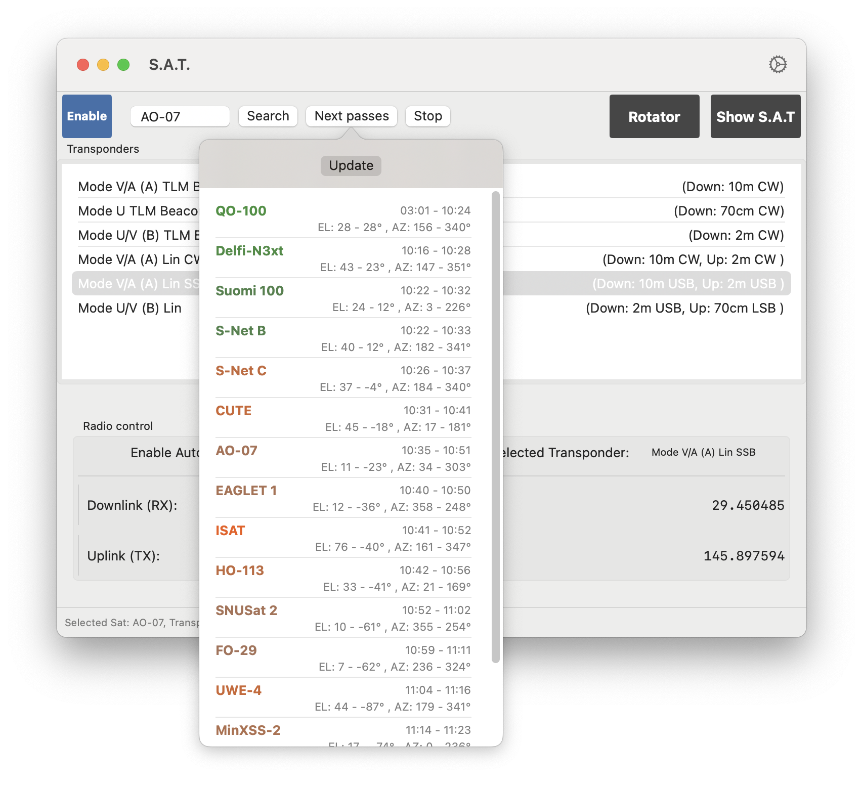
To operate a satellite, tap the “Next Passes” button at the top. You will see a list of satellites currently passing over your location. The color coding indicates the ease or likelihood of establishing a connection. Select a satellite from this list, and the S.A.T. controller will adjust the antenna to point towards it.
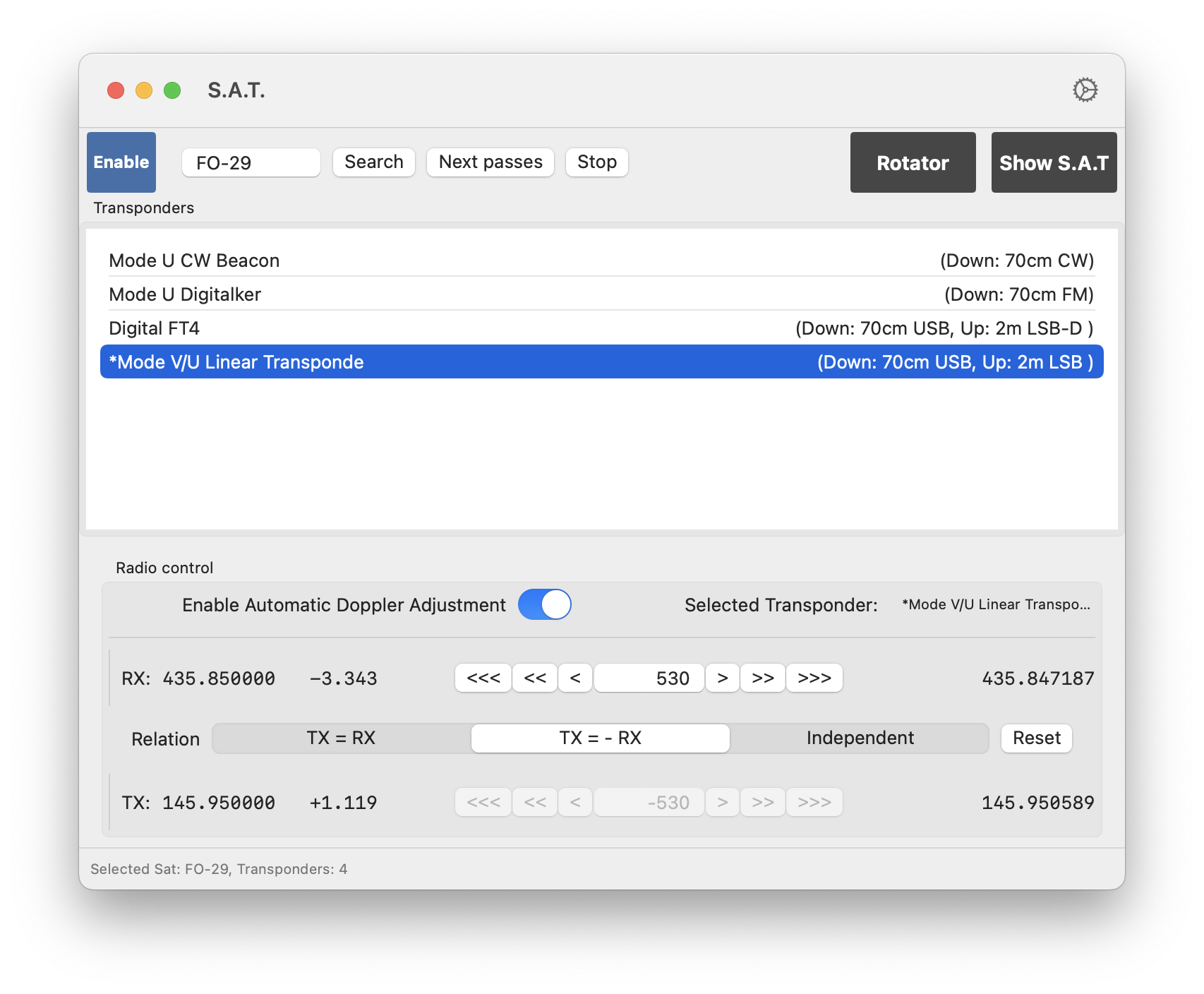
After selecting a satellite, a list of its transponders will appear. Choose the desired transponder. Below, the downlink (RX) and uplink (TX) frequencies, including the Doppler-adjusted frequencies, will be displayed.
Once connected to your radio, you can enable the “Enable automatic Doppler Adjustment” setting, and the radio will automatically adjust its RX and TX frequencies based on the satellite’s location and whether it is approaching or moving away from your position. Simultaneously, the S.A.T. device will adjust the antenna’s elevation and azimuth to maintain alignment with the satellite.
To adjust an additional offset for RX and TX, simply click the arrow buttons located to the left or right of the entry field for manually entering an offset. You can set different offsets for RX and TX, or choose either TX = RX or TX = -RX (which is the most common scenario).
The RX and TX offset can also conveniently adjusted using one of the supported Controller such as the CTR2.
For the radio, consider the following settings:
Avoid using Dual Watch (DW) or SAT Mode as external Doppler adjustments are not allowed in these modes on Icom radios. If you need to use DW or SAT Mode, disable the “Enable Automatic Doppler Adjustment” setting. Otherwise, turn off DW or SAT mode, switch to VFO Mode, and ideally turn off the second VFO.
Note
Always select the main VFO and keep it in VFO Mode.
If the downlink and uplink are on the same bands, use Split mode for your operations as it allows quick switching between RX and TX.
If they are on different bands, ensure the main VFO can operate on both bands. For example, if using an IC-9700 and operating on 2m and 70cm, switch the second VFO (Sub VFO) to 23cm to allow the main VFO to switch between 2m and 70cm.
Note
You can always hit the Stop button at the top to halt the S.A.T. device from moving the antenna rotator and tracking a satellite.
You can also enter the name of a satellite and tap the Search button to look for a specific satellite.
11.3. Hints for Operating in FT4
Operating in FT4 is achievable using the S.A.T. tool with doppler correction, alongside the included FT8 Tool in the app. This setup is effective even when the Uplink and Downlink are on different bands and utilize different modes (e.g., 70cm USB for Downlink and 2m LSB for Uplink). To ensure smooth operation, follow the steps outlined above and confirm that the RX and TX frequencies are correctly set. Open the FT8 Tool and switch the band selection to Manual. Then, select the desired mode (e.g., FT4) and press RX. At this point, the modes for RX and TX will switch to Data mode, allowing you to operate in FT4 as usual. The radio will automatically switch to the appropriate band when toggling between RX and TX.
11.4. Manual Rotator Control
If you wish to manually adjust the satellite’s position, move to a specific satellite manually, or simply use the S.A.T. device as a basic rotator controller, tap the Rotator button to open the manual rotator control interface in the app.
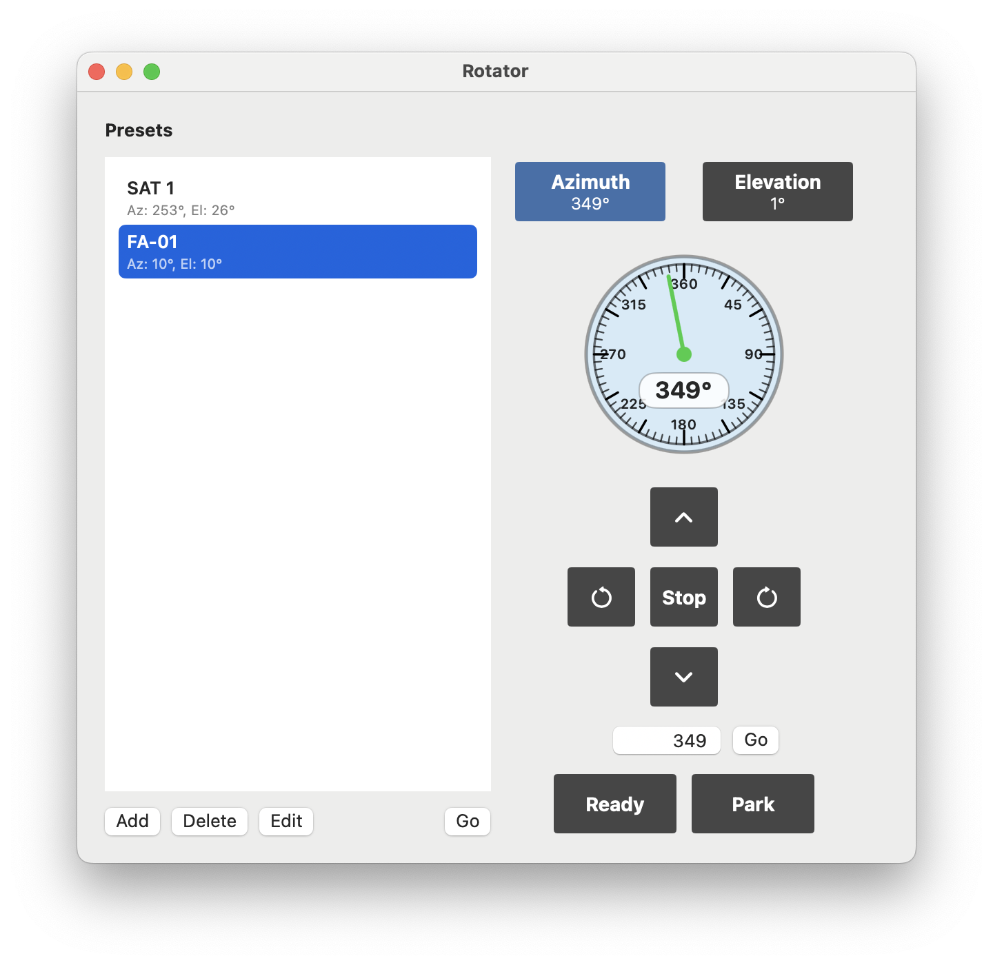
From here, you can direct the rotator to move in any direction using the directional buttons or move to a specific elevation or azimuth angle. Additionally, you can store and recall favorite positions on the left side of this screen.
The Ready and Park buttons will move the antennas to the corresponding locations stored in the S.A.T. device.
11.5. S.A.T. Web Interface
The Show S.A.T. button at the top will open the S.A.T. device’s web interface.
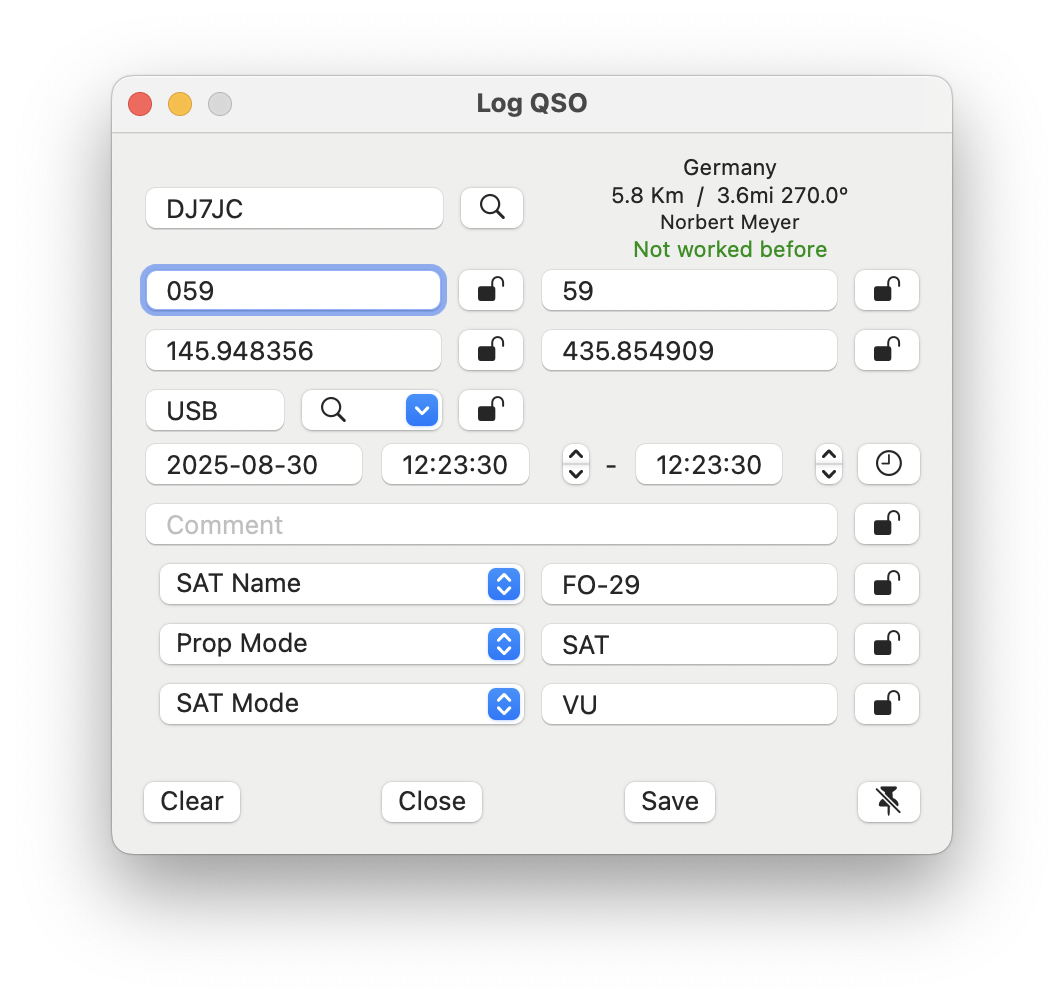
11.6. Logging a SAT QSO
When logging a QSO, the app automatically adds three additional fields for SAT operation: SAT Name, SAT Mode, and Prop Mode.
11.7. Remote access
Accessing the S.A.T. device within your local network poses no issues. However, accessing the S.A.T. over the internet requires a VPN, as the internal server of the S.A.T. device needs to be accessible. This cannot be securely achieved by merely opening a port, as you might for a radio. Therefore, if you wish to access the S.A.T. device over the internet, you must set up a VPN and ensuring that your S.A.T. device is reachable from a remote location with the same IP address as if you were at home.
12. Network Stats
This tool is designed to assist in diagnosing network-related issues.
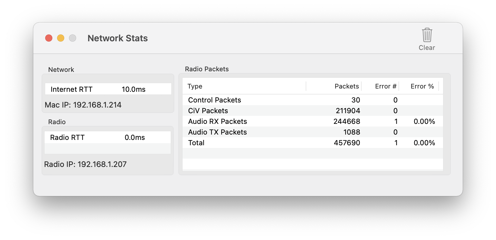
It provides insights into the network traffic to and from your radio.
Internet RTT represents the Round-Trip Time—the duration for a signal to travel to an internet server and back. Ideally, this value should be below 30 – 50ms. Higher readings may suggest problems with your overall network connectivity. Note that this metric is relevant primarily for Call Lookups via the internet and not for the link to your radio.
Radio RTT measures the Round-Trip Time to your radio. On local networks, this should be under 20ms. It is essential that this figure is less than or, at the very least, equal to the Internet RTT. If the Radio RTT is significantly greater (e.g., 1.5 times or double the Internet RTT), this points to local network difficulties, such as improper LAN cables, incorrect FullDuplex/HalfDuplex settings, or WiFi complications.
The Radio Packets section displays the count of received packets for specific types, along with the error tally and rate.
An error rate of up to 0.05% is generally acceptable, as the built-in error correction typically compensates for these without noticeable impact. Errors can occur momentarily, for instance, if the device is overloaded (like when switching to another app temporarily). Nonetheless, persistent errors might indicate underlying network problems.
Monitoring the error rate during transmission is also advisable. An increase in errors while transmitting is a strong indicator of an EMC/RFI issue.
Utilize the Clear button at the bottom to reset the error counter. This is useful for evaluating the impact of any modifications to your setup.
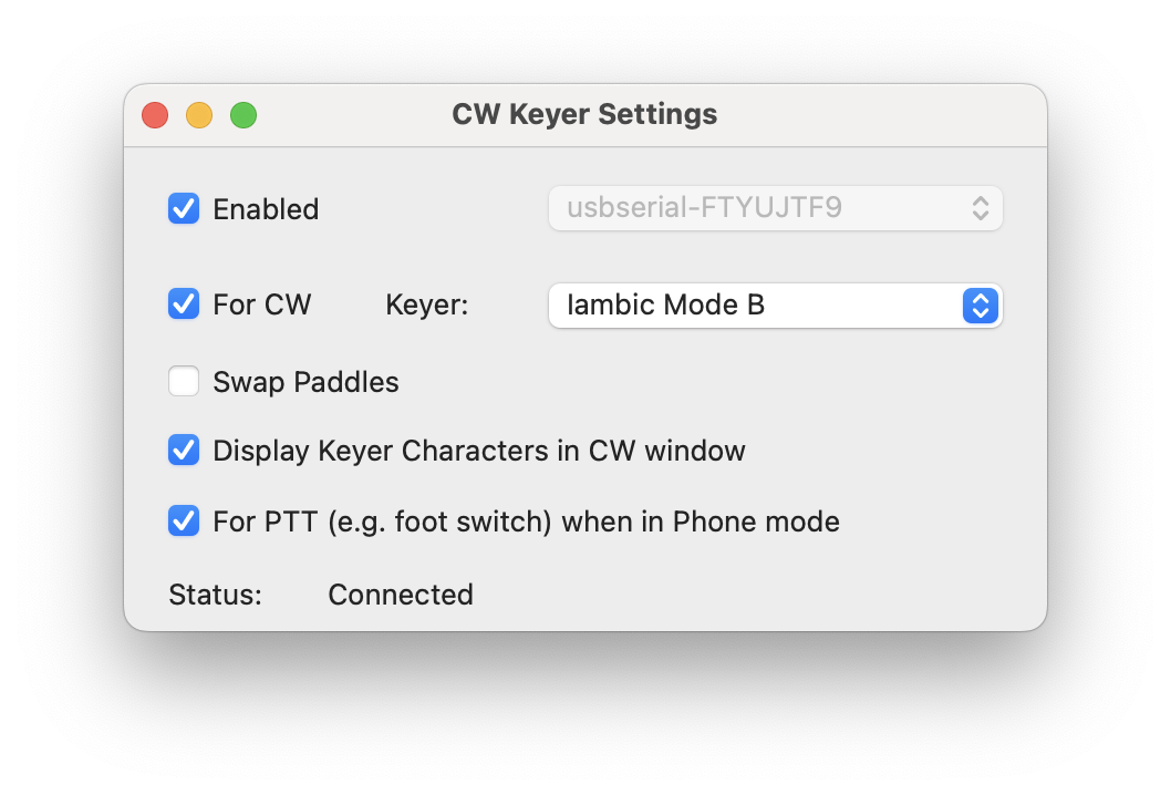
13. CW-Keyer
This tool enables users to generate CW using a CW-Paddle, connected to the USB Port of the Mac.
The USB Serial Cable type and a wiring diagram are provided in the attachment section of this manual.
Additionally, the same USB connection can be utilized for a Foot-Switch in Phone mode.
Note
If your CW Key is directly connected to your Radio. This CW-Keyer will not be used.
After connecting the USB cable to the Mac, the cable’s identifier or name should appear in the Cable selection menu. Make sure to select the appropriate cable before enabling the checkbox.
The Keyer Type selection offers four different key types:
Iambic Mode A
Iambic Mode B
Iambix Mode B Strict
Note
A Straight key or bug is not and can not be supported as it is not possible to key the Radio remotely.
Enabling the Display Keyer Character in CW window option will show all keyed inputs in the CW Panel.
To modify WPM, Side Tone, or other CW parameters, open the CW Panel as if you were generating CW using the keyboard.
14. Band Plan
The Band Plan feature offers a comprehensive frequency guide for all HF HAM Bands tailored to your specific IARU region, including the recommended modes and maximum bandwidth as per IARU guidelines.
Note
To view the Band Plan applicable to your area, please configure your IARU region in the App Settings.
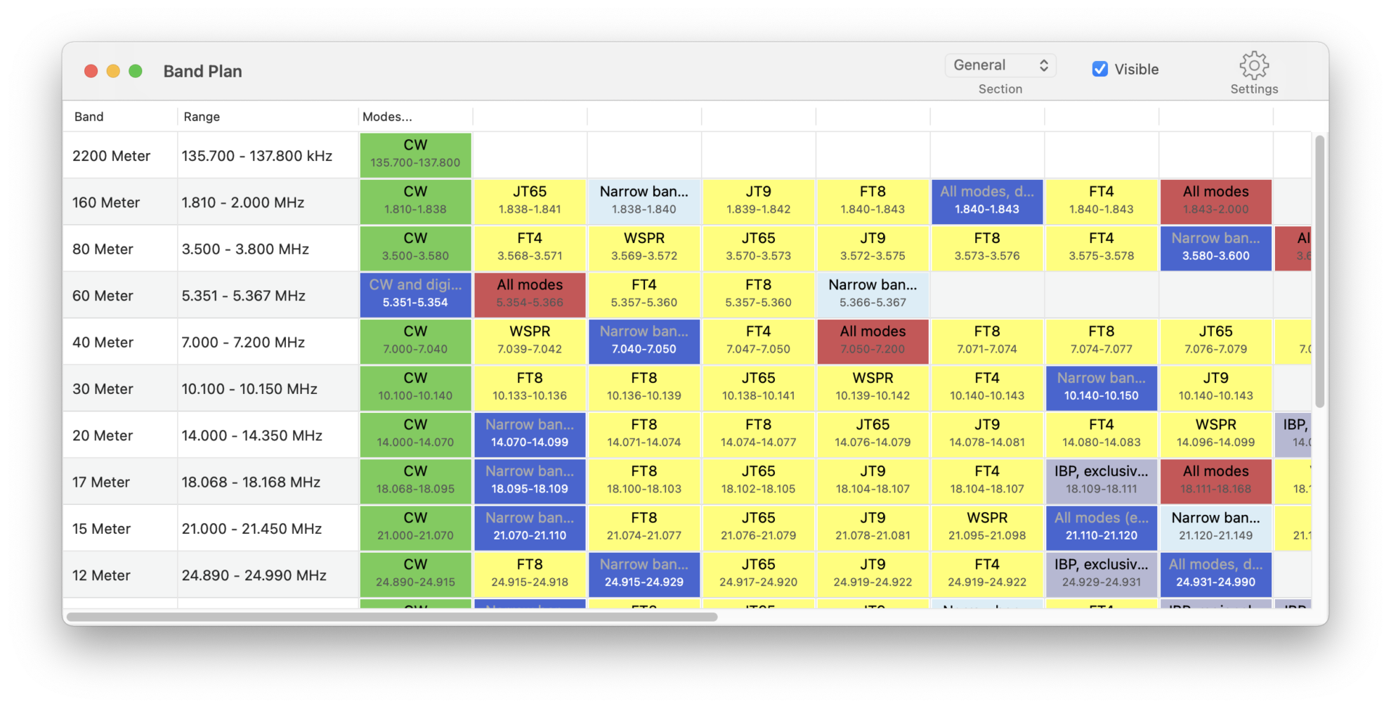
At the top, you can select if you like to see the General or QO-100 SAT Band Plan, which is also included.
Clicking on a band will reveal further details about the selected band.
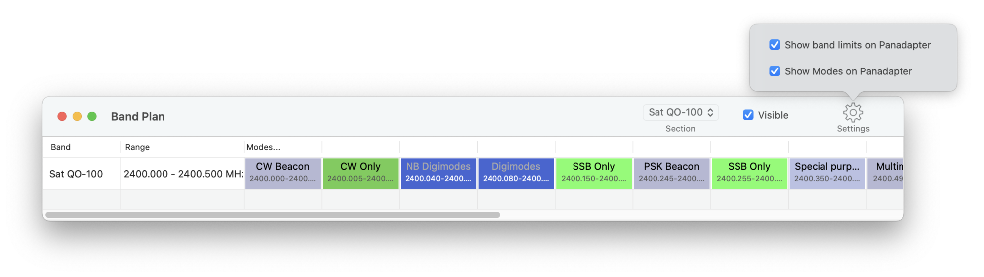
By using the corresponding checkbox, you can make each Band Plan visible or not and by using the Settings menu you can select, whether or not, the Band limits and modes should be visible within on the Waterfall as seen below:
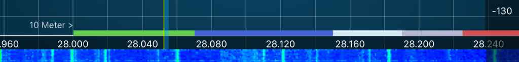
The label “10 Meter >” indicates the Band limits, while the colored lines denote various modes such as CW (green), Digital modes (blue), Narrow modes (cyan), All modes (red), Satellite (yellow), and other designations like Beacons or guard channels (gray).
15. Frequency List
Besides the ability to maintain Radio memories, the App also provides a possibility to maintain a frequency list.
15.1. Difference between Memories and the Frequency list
Memories are limited by the constraints of the Radio. Also, they are stored inside the Radio which is an advantage on one hand as they are available whenever you are using the Radio. On the other hand, they don’t allow maintaining and using a global list of frequencies for different Radios.
The Frequency list tool is a tool to maintain a global list of frequencies for using on multiple Radios. Frequencies are not stored inside the Radio but synchronized via iCloud. However, frequencies here are limited to store a the frequency itself, the mode such as AM, FM etc. a name, comment and tags. Additional parameters like DTCS or TSQL frequency can not be stored here as they are Radio specific.
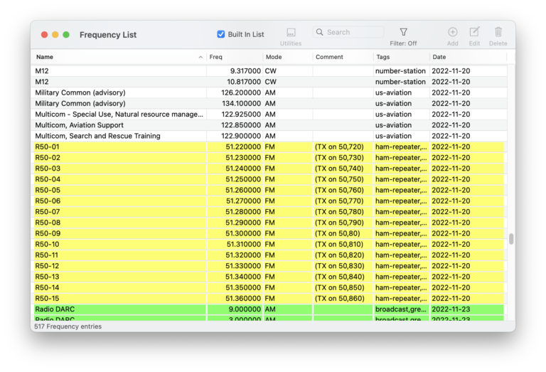
Starting the Frequency list tool will show a window similar to this:
After starting the Logbook tool you will see your last logs.
This list can be sorted by clicking on the column header. You can enter a search term at the top to search for a certain term or filter the list as described further below.
When being connected with a Radio, double-clicking on a line in the list will tune to the corresponding frequency and change the mode. You can also hold the command key while using the arrow keys to change the selection of the list to tune to a frequency.
15.2. Two different lists – Built in and your own
The tool comes with several commonly used frequencies already included. This is the Built in list which will be displayed when the “Built in List” checkbox at the top is checked.
This list will be updated via Data update from time to time.
Note
If you have frequencies that you think might be interesting for others and you like to share, please feel free to send them to me via E-Mail, regardless of their format. I am happy to add them to this list.
The built in list can not be edited but it can be filtered or used as described further below.
If you un-check the “Built In List” checkbox, you will view a list that can be fully maintained by yourself.
Use the Add (+) button at the top to add individual frequencies.
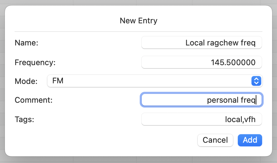
Here you can enter a name, the frequency, select a mode add a comment and tags.
If you are connected to a Radio, Frequency and mode will be pre-filled your current frequency and mode.
Tags are useful for filtering your list. You can enter any number of tags separated by comma (,).
To filter your list, just hit the filter button similar to the other tools of this app.
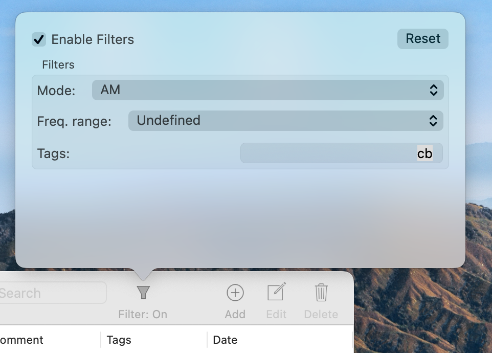
From here you can quickly enable or disable your filters. Selecting a Mode or Frequency range will cause only those frequencies to be listed which are using the given mode and are in the given frequency range.
You can enter one or more tags, separated by comma (,). In this case, you will see all entries that are matching any of the given tags.
15.3. Mass change
Using the Utilities […] menu and selecting Mass Change or by right clicking, you can make changes which will be applied to multiple entries. This way you can change or add comments or tags or change the mode of several entries at once.
If you have multiple lines selected, the changes will only be applied to the selected lines. If no line or just a single line is selected, the changes will be applied to the complete list.
If you enter a tag, all tags of the selected lines will be replaced by this tag. If you would add a plus (+) sign in front of the tag, that tag will be added to all lines. If you would add a minus (-) the tag will be remove if it exists. If you want all tags to be cleared, just enter two minus signs (–) as tag.
Comments can be maintained in the same way.
15.4. Finding duplicates
If you have imported memories from different sources you may end up in multiple equal entries. You can use the Find duplicates tool under the Utilities […] menu to find and merge duplicates.
15.5. Import / Export
Once you have maintained a list of a certain size, I suggest to export that list to keep a backup. For this, just use the Export menu under the Utilities […] menu to write the list to a file.
You can pick the location where the file should be stored and the file name on the file selection screen. The file will contain all information, including comments and tags.
The exported file can be imported back again using the Import menu of the Utilities […] menu. When importing a file, the data will be added to the list so you may want to clear (empty) the whole list if you want it to be overwritten. For this, just press control-a (to select all entries of the list) and hit the Delete Icon at the top. Import formats
The tool can handle multiple different formats. The ideal format however is the format which is used when exporting the frequency list. This is a plain text file, semicolon-separated and with a header.
When importing a file, it must at least contain a header with certain column names. Fields can be separated by comma (,), semicolon (;) or tab which will be auto-detected. The following column headers are expected:
Header |
Value |
|---|---|
freq or frequency |
The frequency in Hz |
mode |
The mode |
name |
The Name |
comment |
The Comment |
tags |
The Tags |
Values of missing columns will receive default values. Extra columns will be ignored.
The majority of commonly available frequency lists can be imported this way. This also includes standard Icom Memory (.mem) files.
Files that are not using the necessary header names as listed above must be edited in a standard text editor before they can be imported.
Files in other formats such as XML or JSon files need to be converted to csv files before they can be imported. There are several online tools on the web that can handle this conversion.
Usually frequency lists are containing the frequency in Hz. If your import file is using kHz or MHz, you also need to edit the file before it can be imported.
16. Scanning
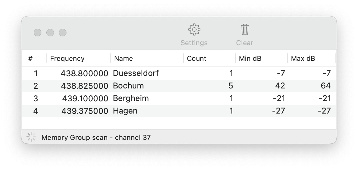
This tool enables users to scan various frequencies. Apart from Memory Group scanning, it runs the Scan on the Radio and compiles the results which will be displayed in a list.
Under Settings, you can define which type of scanning should be performed. Scanning begins after hitting the Start button.
While scanning, all frequencies where a signal was received will be added to the list, including it’s memory name (if available) the number of hits and the minimum or maximum signal strength.
Important
You can also run a Memory Group scan, even though Icom doesn’t provide this possibility for remote access. In this case, this Memory Group Scan will run from inside the App. For this reason, scanning speed is only one channel per second. If you have access to the Radio, you can run a fast Memory Group scan by selecting Memory as Scan type in the Scanning tool, hit the Start button but then start the desired Memory Group Scan at the Radio’s front panel.
Hint
You can mark Memories with Stars (*,**,***). To Scan only Memories marked with Stars, you can select Memory as Scan Type and select the corresponding Stars below the Scan type.
Clicking on a line in the list will stop scanning (if it was running) and tune to the corresponding frequency.
17. Call Lookup
The Call Lookup tool is designed to provide you with detailed information about a specific call sign.
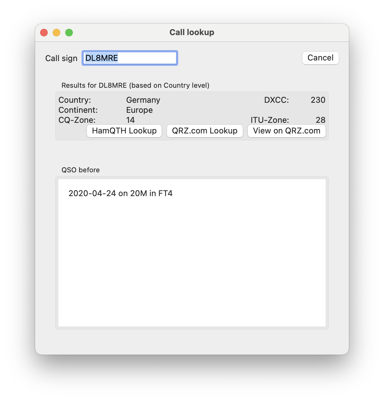
Simply input the call sign into the top entry field to receive immediate basic information such as the Country, DXCC, CQ Zone, and ITU Zone. This data is sourced from the app’s internal database, which is periodically updated. Please note that this information is only accurate at the country level, with the location defaulting to the capital city of the respective country.
Note
The location information provided is based on the capital city of the country associated with the call sign.
Scrolling down, you will find a log of previous QSOs with the specified call sign.
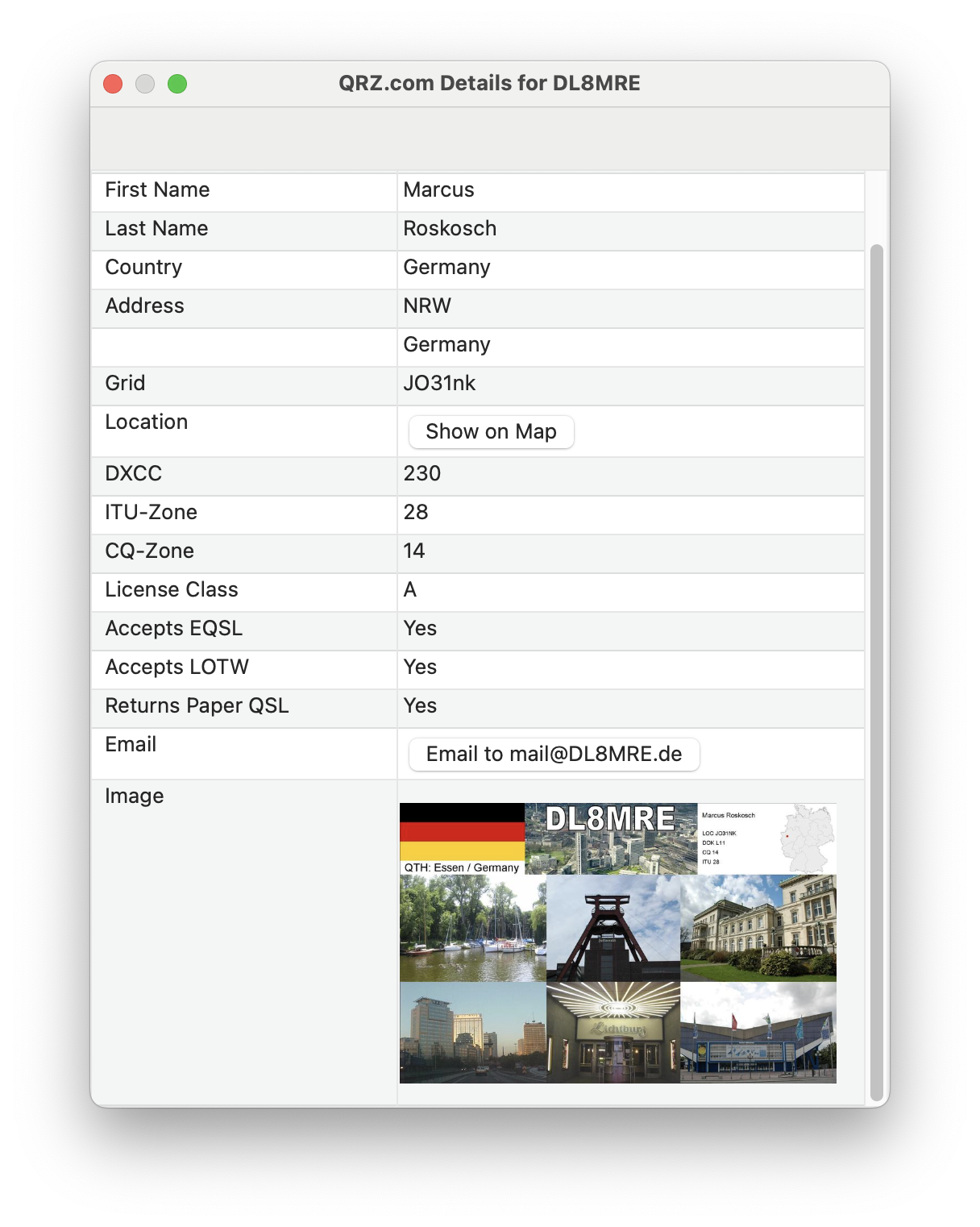
To access more precise and comprehensive details like the operator’s name, exact location, or email address, you can utilize the integrated call lookup services such as HamQTH or QRZ.com. If you have registered accounts with these services, input your credentials in the App Settings for optimal results and a seamless experience using the HamQTH or QRZ.com lookup buttons. If you do not have accounts with these services, you can still use the ‘View on QRZ.com’ button to access the QRZ.com page for the selected call sign.
After conducting a call lookup via HamQTH or QRZ.com, the information displayed in the upper section of the app will be refreshed with the updated data.
Note
To utilize the QRZ.com lookup feature, you must also subscribe to the QRZ.com XML Data service.
By using one of these services, the Call Lookup window will reflect the enhanced data obtained, ensuring you have the most accurate information available.
18. DX-Cluster
The DX-Cluster Tool connects you to a variety of pre-defined global DX-Cluster databases or your local CW-Skimmer, displaying Spots directly on the Waterfall. You can also instantly tune to a Spot’s frequency by simply tapping on its entry in the list.
Upon launching the DX-Cluster Tool, click on ‘Start’ to begin retrieving data from the selected DX-Cluster server.
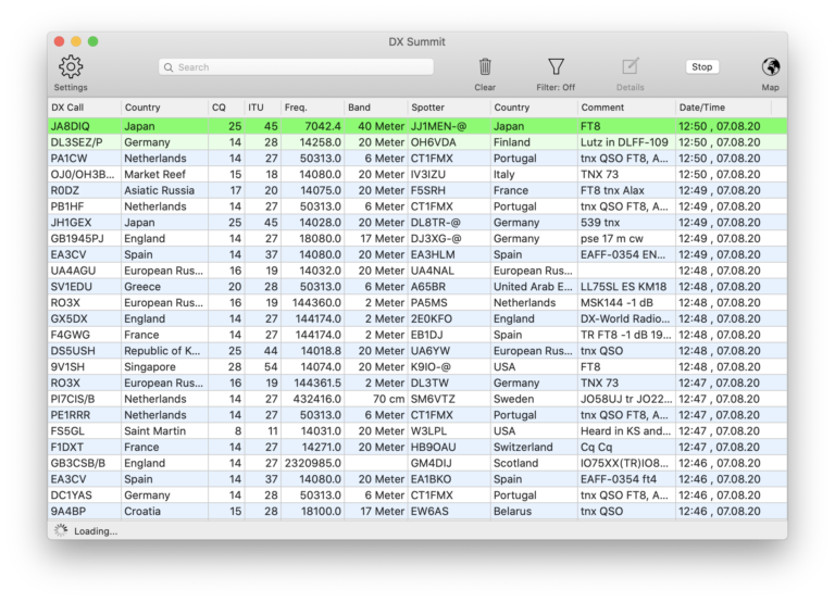
Double-clicking on a Spot within the list will prompt your Radio to tune to that Spot’s frequency.
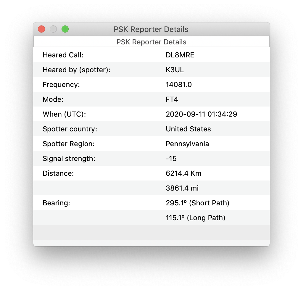
Selecting a Spot and clicking on ‘Details’ (or right-clicking and selecting ‘Show Details’) will reveal additional information about the Spotter and the Call.
To access various Filter options, click on the Filter Icon at the top:
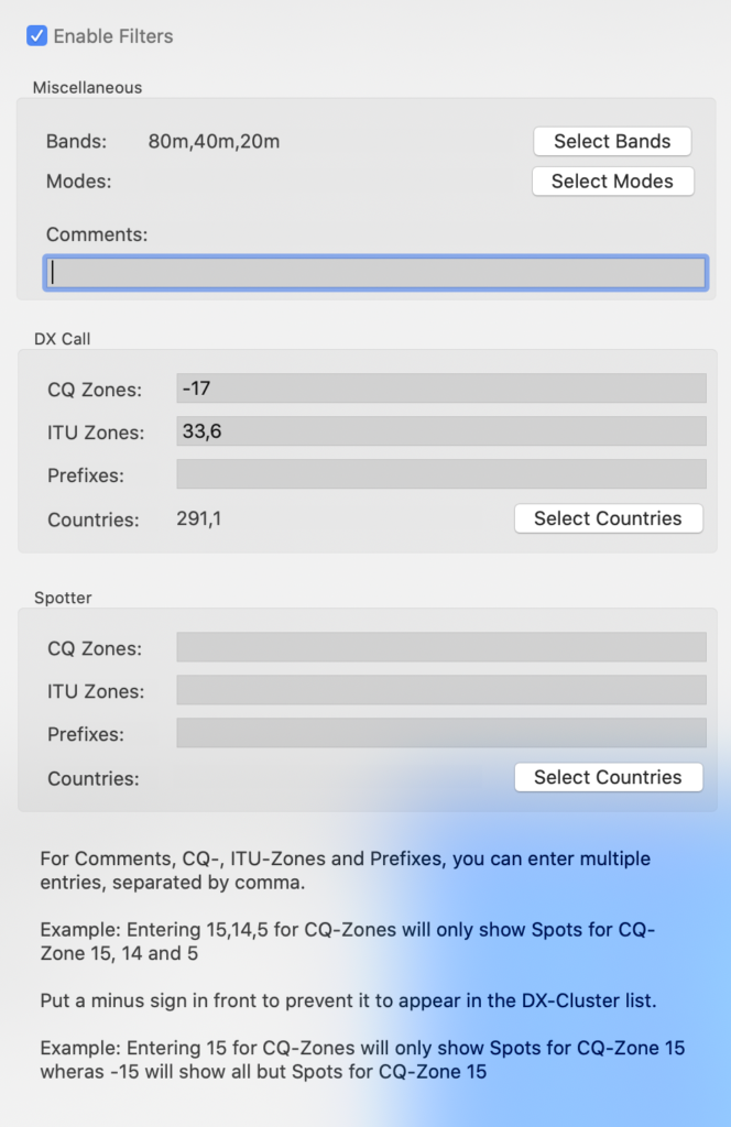
Please note that you can input single or multiple values in the fields, separated by commas, as indicated at the bottom of the screen.
You have the option to enable or disable these filters at the top of the screen.
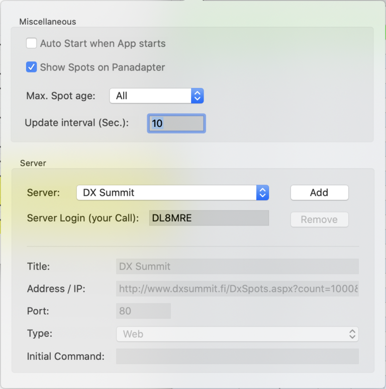
Clicking on the Settings (gear) Icon allows you to modify various aspects of the DX-Cluster Tool. You can select from the predefined servers or add a new one by clicking the ‘Add’ button.
Note
When adding a new server, some servers require a login which is usually the call sign. This will get sent automatically if entered. If additional information needs to be sent, you can enter this information in the initial command field. A \n can be entered to send a new line. Some servers allow to use the initial command sh/fdx 100 to let the last 100 spots to get sent along with the first connection. To submit this command to the server uppon connection, enter \nsh/fdx 100\n as initial command (note the slash and backslash here).
18.1. Map
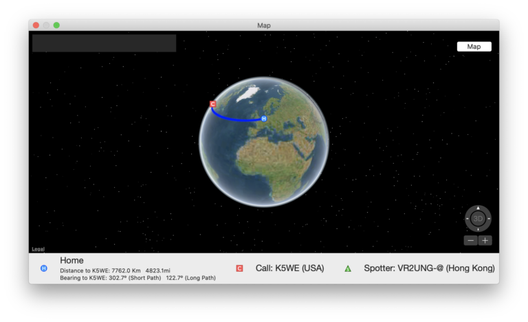
To view all current DX-Cluster Spots on a map, click on the map icon at the top.
Alternatively, select “Show on Map” in the details view of a DX-Cluster Spot to see your distance and bearing to the Spot.
19. PSK Reporter
PSK Reporter is an excellent automatic propagation reporting tool for digital modes, including FT8 and FT4.
HAM operators can leverage PSK Reporter to gain a nearly instantaneous overview of the current DX conditions and determine who is receiving their signals globally.
This App seamlessly integrates with PSK Reporter in two distinct functions.
19.1. Submitting PSK Reporter Spots
PSK Reporter thrives on the contributions of reception reports from the HAM community. This App can automatically relay FT8 and FT4 reports to PSK Reporter when activated (accessible under Settings within the FT8 Tool or the PSK Reporter Tool).
Once enabled, the App will submit a list of received FT8/FT4 signals to PSK Reporter at five-minute intervals. Beyond the optional details about your antenna, no further configuration is necessary.
19.2. Viewing PSK Reporter Results
Conversely, the PSK Reporter Tool allows you to view the roster of stations that have received your signal.
To obtain a report of stations that can receive you, initiate a QSO or a test transmission on your band of interest. Then, launch the PSK Reporter Tool, enter your callsign at the top of the window (if it isn’t already pre-filled), and press the start button.
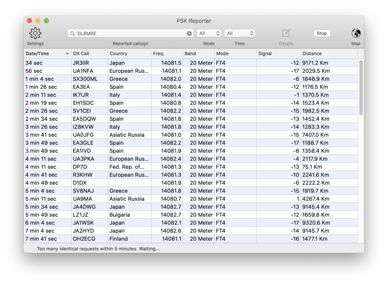
After the list populates with reports, you can select an entry for expanded details.
Please note that it may take up to 15 minutes post-transmission to view your results. This delay is due to each contributing listener updating their reports every five minutes, and the PSK Reporter system not allowing data retrieval more frequently than this interval. If you attempt to refresh the data before five minutes have elapsed, an appropriate message will be displayed at the bottom of the window.
To refine the displayed results, use the Filter Icon at the top to select a specific Mode and Time frame.
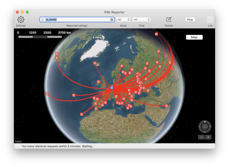
Enhance your data analysis by visualizing all receiving locations on a map. Switch to map mode by clicking the Map Icon at the top.
For an interactive experience, the map mode presents all receiving stations’ locations.
Remember, the more HAMs contribute their reports, the richer the data set becomes, enhancing the utility of PSK Reporter for everyone in the amateur radio community.
20. Alerts
Alerts are designed to notify you with an alarm and highlight entries in the Logbook, DX-Cluster, FT8/FT4, or RTTY tools when specific criteria are met.
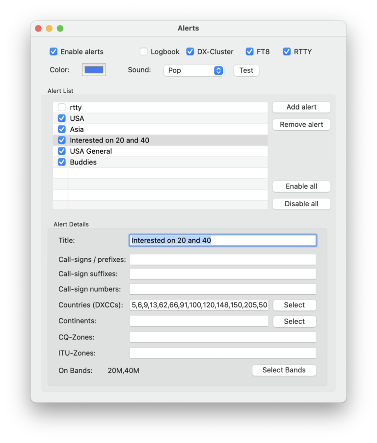
You have the ability to configure multiple Alert settings. Click the ‘Add alert’ button to create a new setting, which you can then fine-tune in the ‘Alert Details’ section.
Within the title area, input the desired criteria for an alert.
For most fields, you can input multiple terms or numbers (e.g., multiple prefixes) separated by a comma (,), indicating that any of these prefixes will trigger the alert.
When you apply more than one criterion (e.g., prefixes and bands), all criteria must be met for the alert to sound.
Hint
As a general guide: horizontal = ‘OR’, vertical = ‘AND’
In the given example, this means that the alert will be activated if any of the specified countries (DXCC 5,6,9…) are spotted on the 20 or 40 Meter bands.
At the top of the Alert tool, you can choose a color for highlighting alerts and select the sound to be played. It’s possible to enable or disable all alerts simultaneously or individually for each tool. Once alerts are activated, you can also swiftly toggle them on or off from within each tool using the alerts toolbar icon.
The logbook will merely highlight matching entries without producing an alert sound. This feature can be beneficial for testing your alert settings, as it allows you to identify which logbook entries meet your specified criteria.
21. Logbook
The included Logbook was implemented with the idea in mind to offer a quick and easy logging feature to this App which should already provide all basic requirements for day to day logging.
The integrated Logbook is designed to provide a quick and efficient logging solution within the App, meeting all the essential needs for routine logging activities.
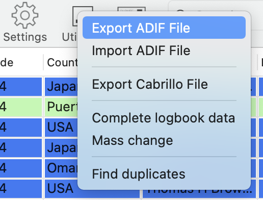
You can export (and import) logs in ADIF format to facilitate logbook data interchange with other logging programs, or export your logs in Cabrillo format for contest submissions.
Note
To export a specific segment of your complete log, apply a filter to narrow down your logbook entries and then enable the Export only filtered Log entries option in the Settings.
Upon launching the Logbook feature, your most recent log entries will be displayed.
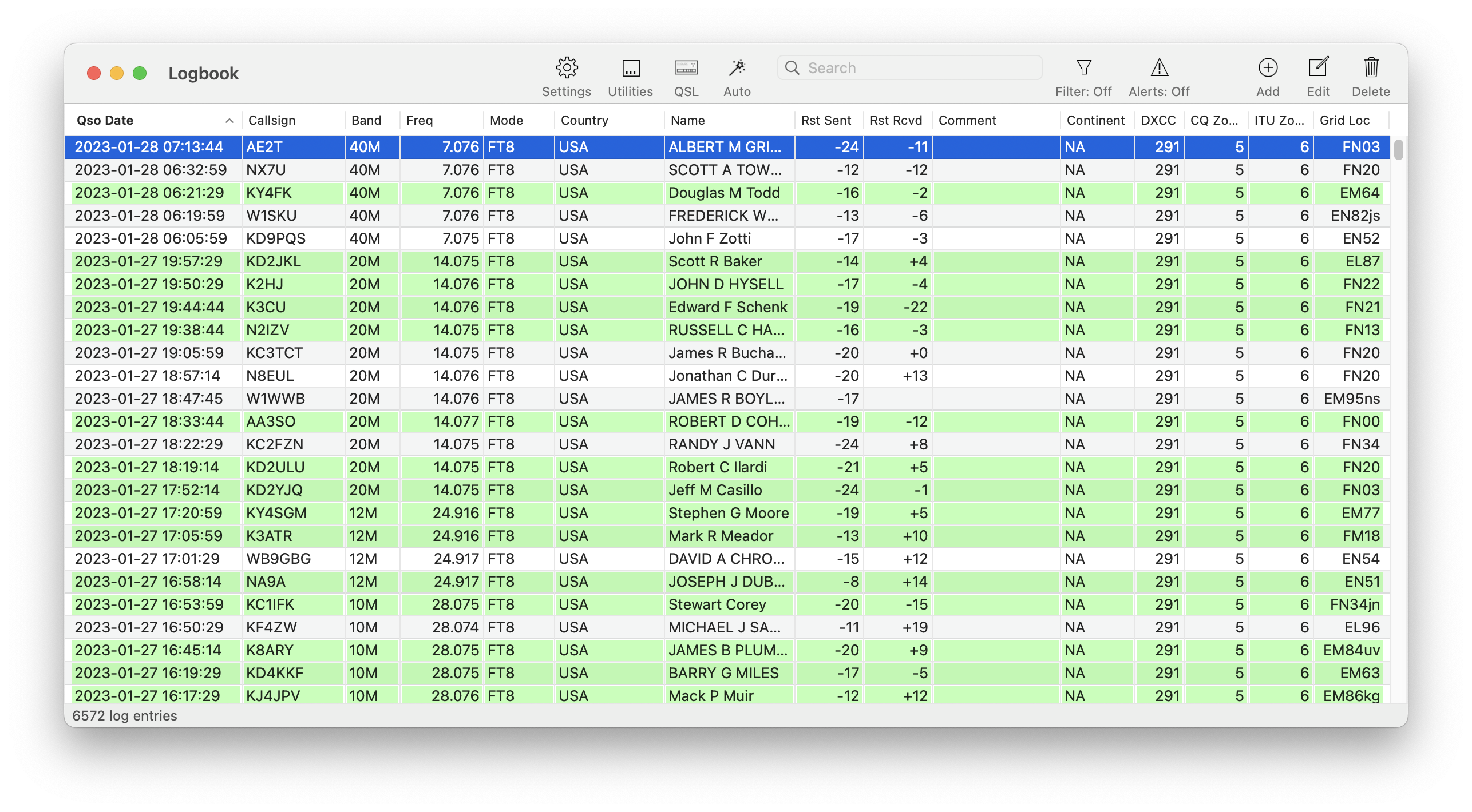
Sorting the list is as simple as clicking on the column headers. A second click will reverse the sort order.
To modify an existing QSO entry, select the entry and click on edit, or double-click the entry.
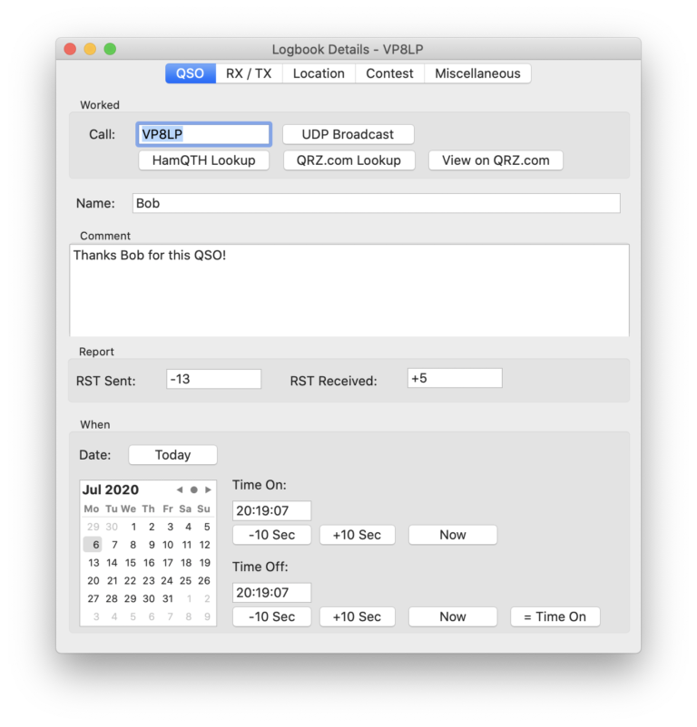
Here, you have the flexibility to manually adjust all log fields or have them auto-populated using the HamQTH or QRZ.com lookup functions by pressing the corresponding button.
21.1. Settings
The logbook offers a variety of customization options.
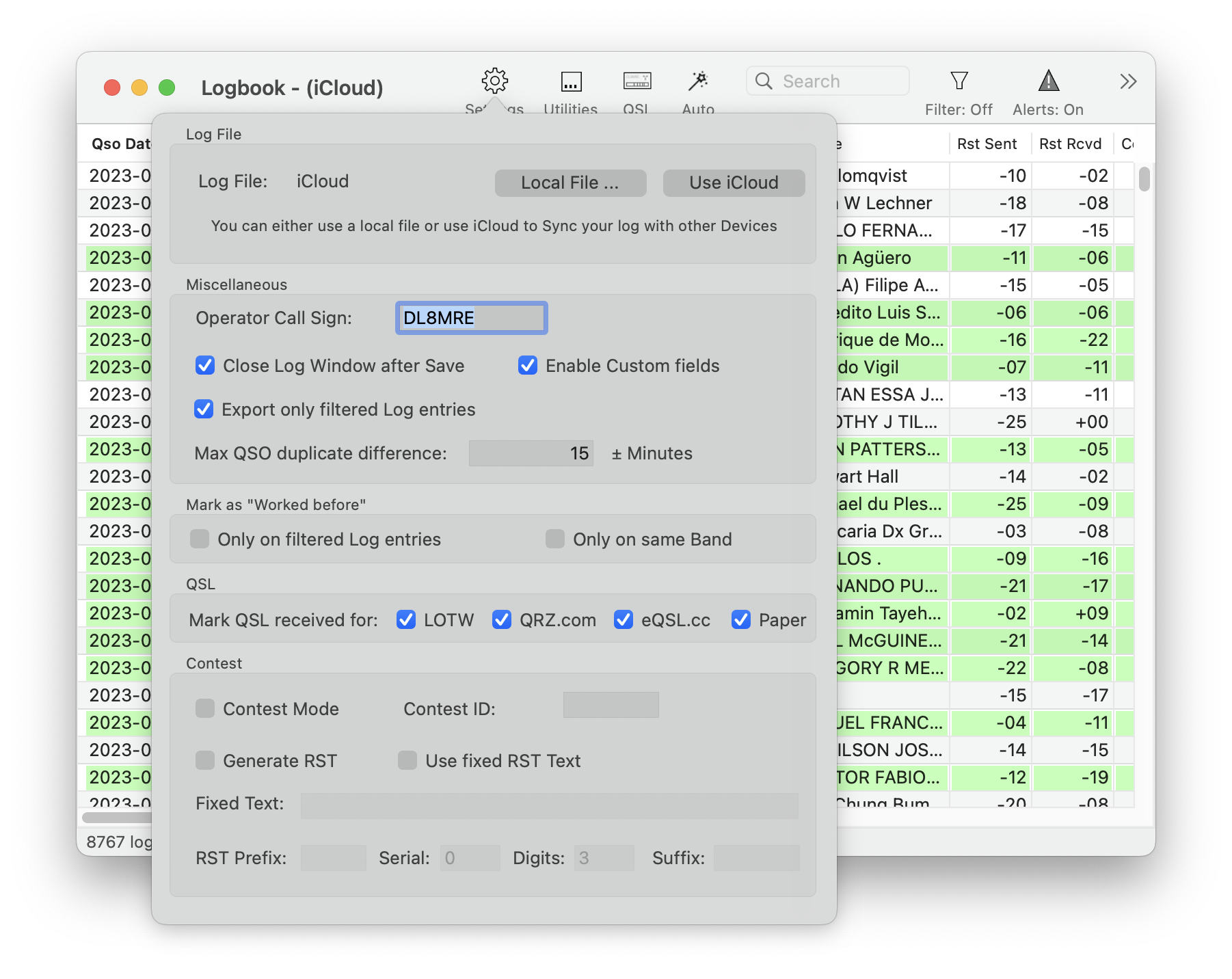
In the Log File section, you can opt to save your log locally on your hard drive or use iCloud for storage. When utilizing iCloud, your log will automatically sync across all your devices. To enable this feature, iCloud must be activated in the App Settings, and both iCloud and iCloud Drive must be turned on for your Mac and any other devices you wish to use for log sharing. This synchronization allows you to access your log on other Macs, iPhones, and iPads with FT-Control, SDR-Control, SmartSDR, and HAM-Toolbox Apps.
The Operator Call Sign is recorded in your log with each new QSO. This call sign may differ from the primary call sign specified in the App Settings. For example, you might use the /P suffix for portable operations.
Tools like the FT8 Tool will highlight previously contacted call signs in a distinct color. The Mark as “Worked before” setting allows you to define when a call sign should be considered as having been “worked before.”
In the Contest settings, the logging tool can auto-fill the RST fields and tag QSOs in your log with the appropriate Contest ID. Additionally, the auto-generated Serial numbers can be utilized as variables in Macros.
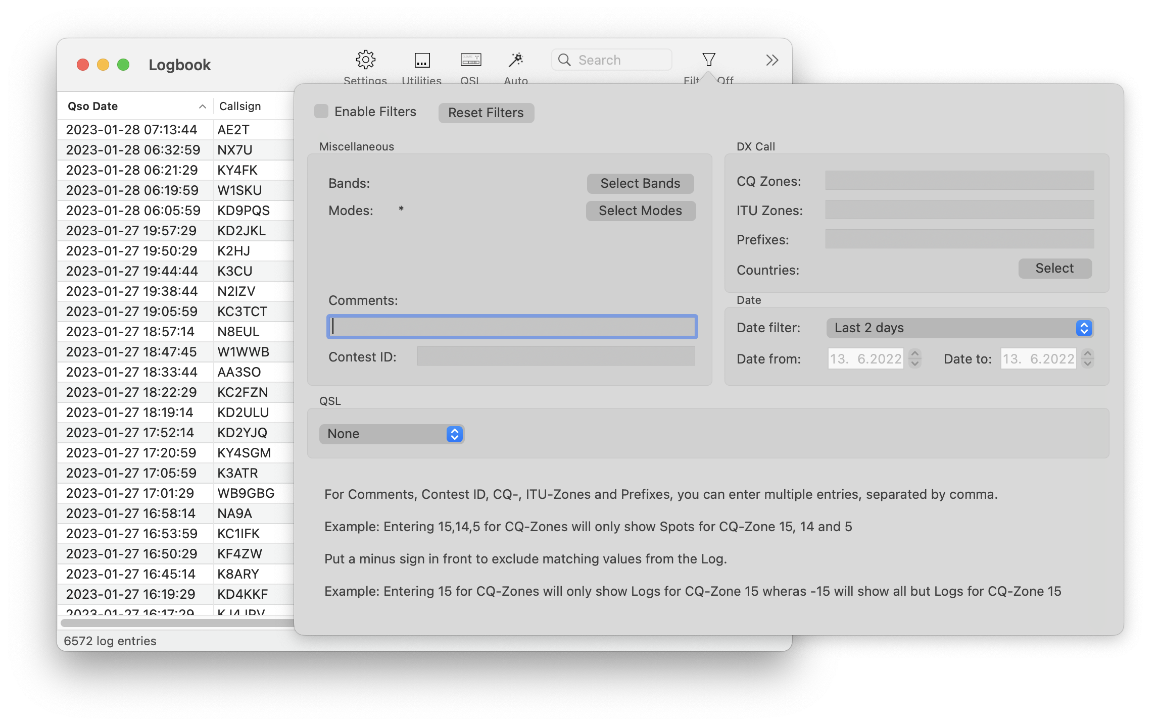
21.2. Filtering
The Logbook includes a filtering feature that can be accessed using the Filter button.
21.3. Utilities
The Utilities button allows you to Import or Export your logbook.
Hint
If you wish to export specific segments of your Logbook, utilize the logbook filter (e.g., to isolate logs from the past 24 hours) and activate the Export only filtered Log Entries option in the Logbook Settings.
21.3.1. Complete logbook data
The Complete logbook data feature meticulously processes each logbook entry to automatically populate missing information based on the following configurations:
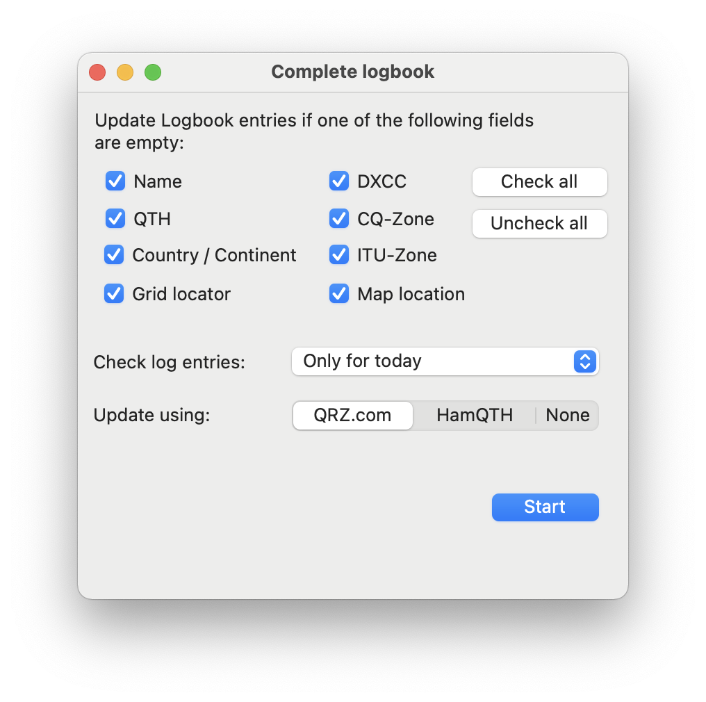
This function allows for the automatic addition of Names, QTHs, Countries, etc., of your QSO partners after concluding multiple QSOs. If you choose ‘None’ for the “Update using:” option, the system will only fill in fields that are evidently missing, such as an empty Band field when the frequency has been inputted.
21.3.2. Mass changes
To change many fields at once, for example add the contest ID to all QSOs of the past two days, you can use the Mass change utility.
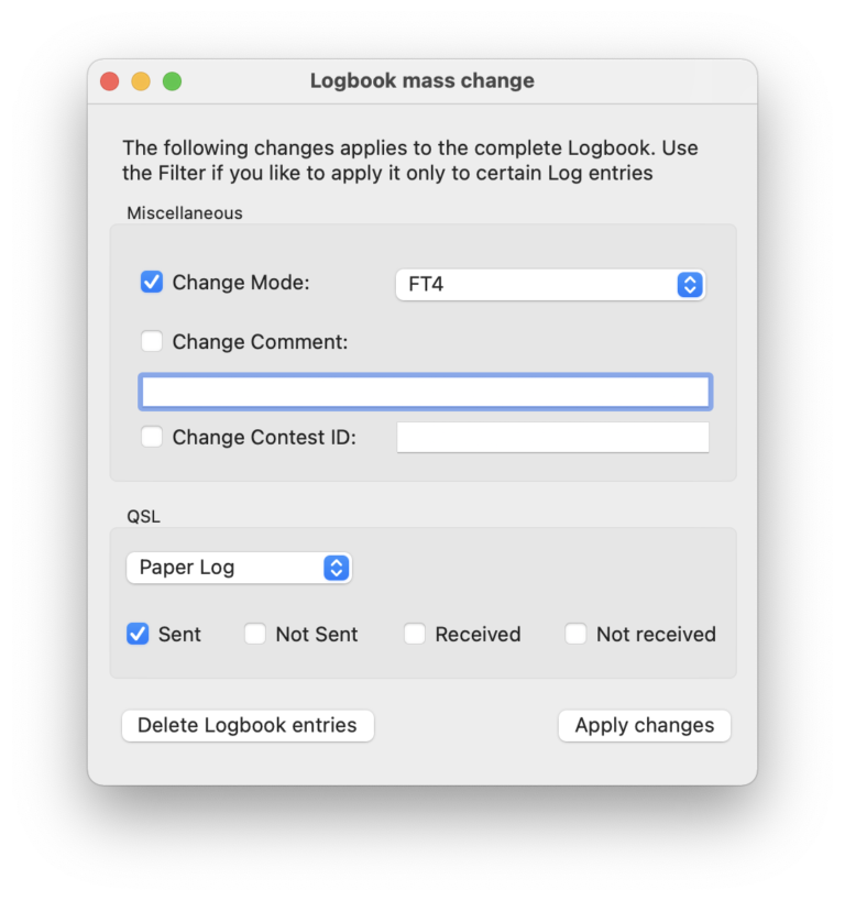
Only the ticked (checked) changes will be applied when hitting Apply changes. To apply the changes only to certain logbook entries, use the filter. For the comment field, you can use a + prefix to let the text after the + be appended to existing comments. A – sign will do the opposite and remove any occurrences of the text after a -. If no + or – is used, the new comment will always override any existing comment.
From here, you can also delete the entire logbook or the filtered logbook entries. For example, if you like to remove all logbook entries older than four years, just use the date filter to filter from (e.g. 1.1.1900) to a date four years ago. After applying the filter, you should only see older log entries. Now you can use the Delete Logbook entries button in the Mass change utility to delete those old entries.
21.3.3. Find duplicates
The find duplicates utility can be used to identify and merge duplicate logbook entries. Entries are considered duplicate if they contain the same call-sign, band and the time of the QSO is nearly the same. The maximum time difference between duplicate QSOs can be entered in the Logbook settings. You are able to review found duplicate QSOs before letting them be merged.
21.4. Logging a New QSO
To log a new QSO, you have several options available:
Within the Logbook Tool, click the (+) Add Icon.
From the View menu, select “Log new QSO.”
When the Waterfall is the active window, press Option-Command-L (or any other assigned keyboard shortcut).
The FT8 Tool will automatically open the logging window after completing a QSO (only if auto-logging is turned off).
The logging window that appears will be pre-filled with information based on the current VFO settings:
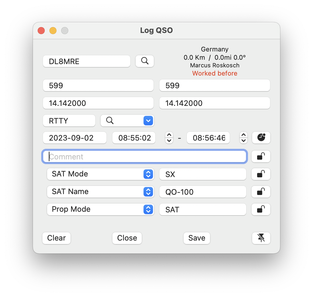
To log a new QSO, simply input the callsign of the station you contacted and click the “Save” button. This will record the contact information in your Logbook.
Next to the callsign entry field, you’ll see additional data about the station, such as QTH (location), distance in kilometers and miles, and both short path (SP) and long path (LP) details. This section also indicates if the callsign is already in your Logbook.
Click the Spy-Glass button for a detailed lookup of the callsign, which will provide more comprehensive information.
21.4.1. Time Stamps
The QSO Start Time is set to the moment you open the log entry window. To update the QSO End Time automatically, click the black clock icon to the right of the time display; this will refresh the end time every second.
21.4.2. Field Locking
Some fields have a lock icon on their right. By enabling this lock, the data you’ve entered in these fields will stay unchanged, even after saving and starting a new QSO entry. This is handy for details that don’t change across multiple QSOs.
21.4.3. Custom Fields
If you activate Custom Fields in the Logbook Settings, three additional input fields will become available. For each, you can choose the corresponding ADIF (Amateur Data Interchange Format) field from a dropdown menu.
Custom fields are particularly useful for niche activities like POTA (Parks on the Air), SOTA (Summits on the Air), SAT-Mode (Satellite Mode), or any other operation where you need to log specific QSO details not usually required.
21.4.4. Keep the Log Window Open
In the bottom-right corner of the window, there’s a push-pin icon that determines whether the window closes after saving a QSO. If the push-pin icon is crossed out, the window will close upon clicking “Save.” If the icon is not crossed out, the window will clear the current entry fields and stay open for efficient, consecutive logging.
21.5. Log Submission to Other Apps via UDP
For HAM radio operators who wish to integrate their logging activities with other software on their Mac or Windows PC, our App offers a seamless UDP log submission feature.
This convenient functionality can be activated within the App Settings. Once enabled, every new log entry you make will automatically be transmitted to your chosen logging program. Additionally, the Log detail screen includes a “UDP Broadcast” button, allowing you to manually send any previous or modified log entries.
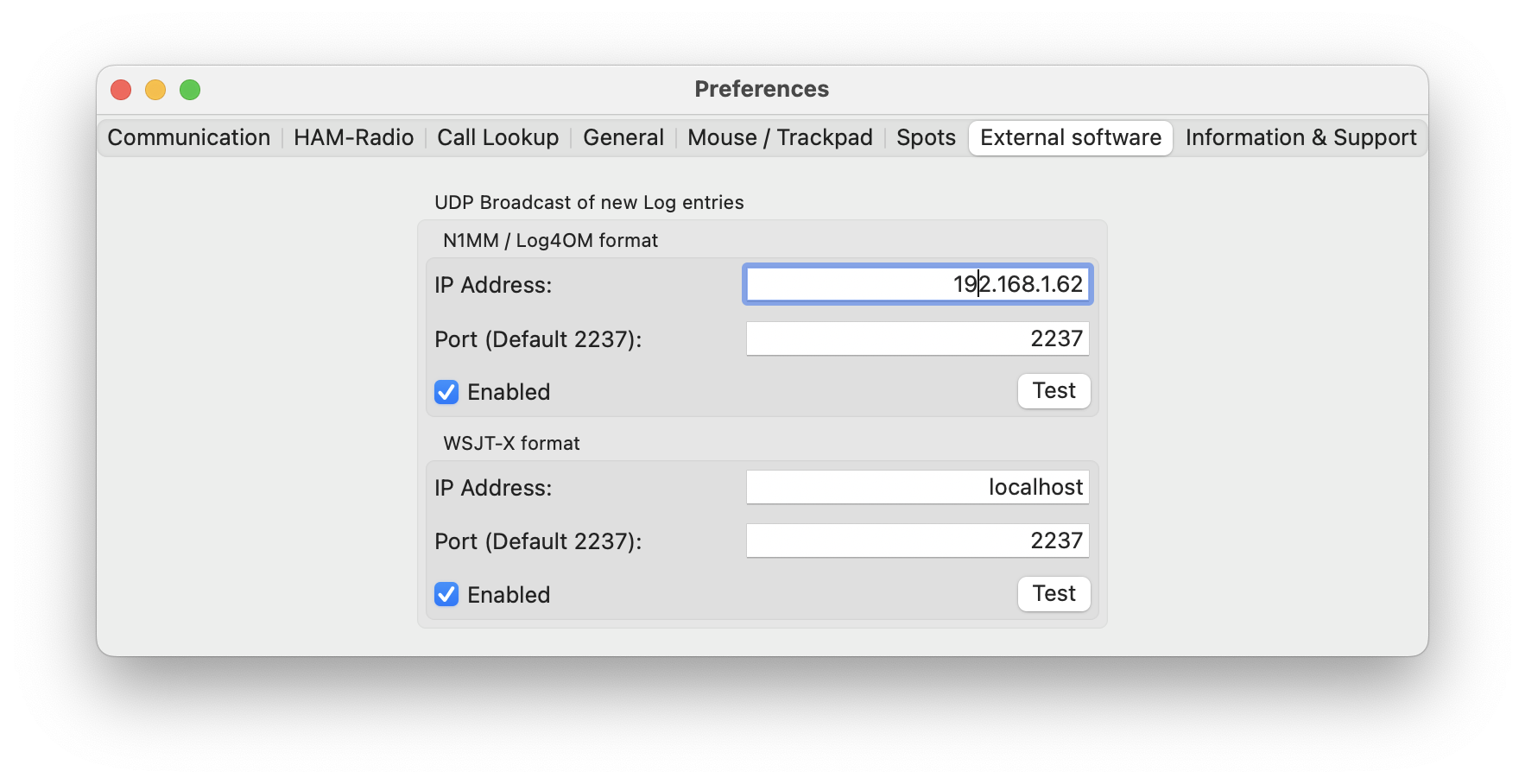
To set up UDP Log transmission, input the IP Address and the specific UDP Port of the computer running your preferred logging software. If the software is operating on the same Mac, simply use the loopback IP Address, 127.0.0.1.
This App is compatible with multiple UDP log submission standards, catering to a variety of user preferences:
N1MM or Log4OM Format
This format is recognized by N1MM, Log4OM, and other primarily PC-based logging programs.
WSJT-X Format
Adopted by WSJT-X, this format is compatible with any logging software capable of receiving WSJT-X UDP logging data.
The appropriate port for each format will depend on the logging program you are using. Some programs permit custom port configuration, while others may require a default port number. It is crucial to ensure that the port number specified in the App matches the one set in your logging software.
By using the Test button, you can dispatch a trial log entry to confirm the successful reception by your logging program.
21.6. QSO Confirmations (QSL)
You can submit Logged QSOs to LOTW, QRZ.com, ClubLog, eQSL.cc, and CloudLog. QSO confirmations can be received from LOTW and QRZ.com.
Note
Before you submit any QSO to any of these services, please double-check if you have entered all the necessary information under SDR-Control → Settings in the HAM-Radio tab. The “Logging information” section is particularly important because some of this information will be submitted along with your log.
The QSL feature can be accessed by clicking the QSL icon at the top of the Logbook screen.
Upon clicking this icon, the following QSL screen will appear:
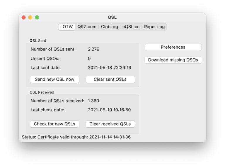
There is a tab for each supported QSL Service. Each Service (except Paper Log) requires credentials to be entered to use the service.
21.6.1. Preferences
To enter your credentials, select the appropriate tab for the Service you wish to configure and click on the Preferences button.
Each Service requires different information.
For QRZ.com, you need to obtain your QRZ.com API Key from the QRZ.com website. To do this, log in to QRZ.com, click on ‘My Logbook’ (located under the dropdown menu with your callsign), and then click on ‘Settings’ on the right. In the ‘QRZ Logbook API’ section, you can reveal your API Key by clicking on ‘Show’. Copy and paste this API Key into the QRZ.com Preferences screen in the app. Please note: Access to this feature requires a QRZ.com subscription. For more information, visit the QRZ.com website.
For LOTW, the preferences screen is as follows:
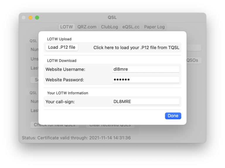
Here, you must upload a .P12 file and enter your LOTW website login credentials. The LOTW .P12 file is generated using the TQSL software from LOTW.
Warning
TQSL Version 2.7.1 is incompatible with macOS. To create a macOS-compatible .p12 file, use TQSL Version 2.7.2 or newer and enable macOS compatibility. Open TQSL, go to ‘TQSL -> Preferences’, and check ‘Export P12 files compatible with Apple Keychain’ and ‘Enable passphrases for Callsign Certificates.’ These settings are specific to the macOS version of TQSL. Windows users should use an older version, like 2.6.5, which is macOS compatible.
Launch TQSL, go to the ‘Callsign Certificates’ tab, and select your certificate from the ‘tQSL Certificates’ list.
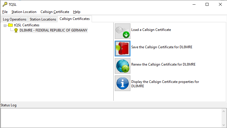
Then click on “Save Callsign Certificate…” on the right. Choose a directory and filename for the file.
You will also be prompted to create a passphrase. It’s important to use a passphrase for security, and it should be different from your LOTW password.
Important
On a Mac, all Certificate files must be password-protected. If you have a previously created .P12 file without a passphrase, it will not work on a Mac. You must create a new file with a passphrase.
These steps are applicable to both Windows and Mac users. In the SDR-Control LOTW QSL Preferences, click “Load .P12 file” and navigate to the file’s location. When prompted, enter the passphrase you created earlier.
Note
The App securely stores all information in the local macOS Keychain. Consequently, macOS may ask for your Mac’s password. This is distinct from your LOTW Password or the passphrase.
For CloudLog, input your CloudLog server’s address, including ‘http://’ or ‘https://’. If your server uses a non-standard port (not 80 or 443), append it to the address after a colon. Enter the Station ID and API Key as well. For additional details, refer to the CloudLog website.
21.6.2. Send New QSLs
When you have “Unsent QSLs” (QSOs that you’ve logged but haven’t yet submitted), simply press the “Send new QSL now” button to submit these pending QSOs to the chosen Service.
21.6.3. Check for New QSLs
For both LOTW and QRZ.com, it’s possible to retrieve QSO confirmations from other HAMS for the QSOs in your logbook. To do this, click the “Check for new QSLs” button.
21.6.4. Download QSOs
With LOTW and QRZ.com, you also have the option to download all the QSOs stored on these platforms. This is particularly helpful if you’ve misplaced some or all QSOs in your Log. By clicking the button, all QSOs will be imported into your Logbook. However, be aware that LOTW and QRZ.com may not retain every possible QSO field. After downloading QSOs in this manner, you might notice duplicates in your log. To tidy up your log, utilize the “Find duplicates” feature found in Utilities.
21.6.5. QSLs in Logbook
Highlight all QSOs for which you’ve received a confirmation by selecting LOTW and/or QRZ.com under QSL in the Logbook Settings.
Moreover, each QSO in the log has a QSL tab on the QSO Details screen.
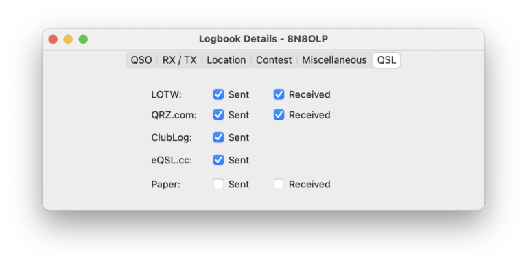
On this screen, you can manually select or deselect QSO confirmations (for example, for Paper QSL cards you have sent).
If you need to mark multiple QSOs simultaneously, apply the Filter feature of the Logbook to isolate the desired QSOs and then use the “Mass change” Utility.
22. POTA
The POTA Tool presents Parks on the Air (POTA) spots in a manner akin to how the DX-Cluster tool displays regular spots.
POTA Spots can be visualized on the Waterfall. You have the capability to swiftly navigate to the specific frequency of a POTA Spot and import Park details into the Logging Window.
Upon initiating the POTA Tool, within a brief interval, you will observe all spotted POTA stations.
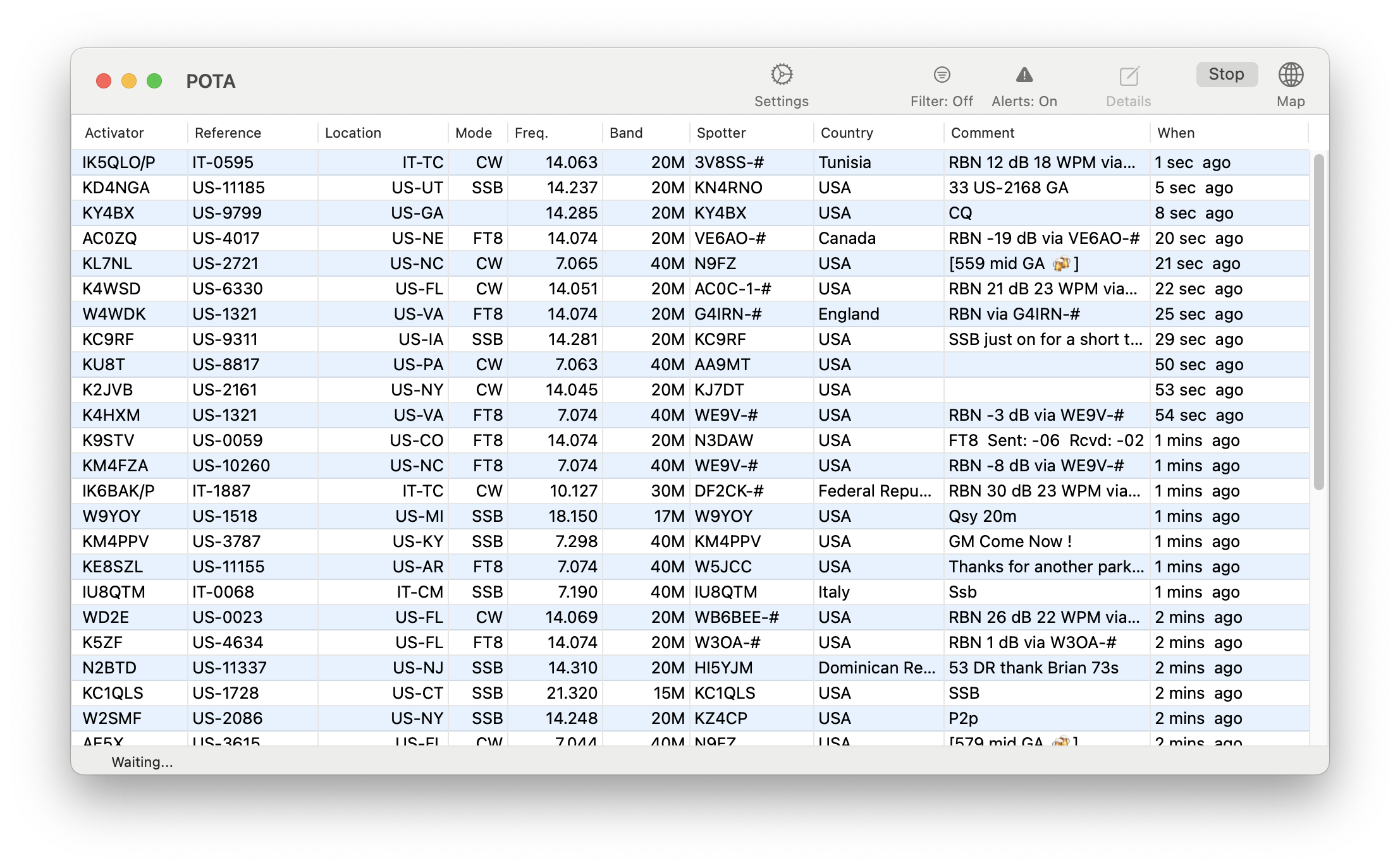
By right-clicking on an entry in this list, you can access additional information about the Park, the Activator, or adjust your Radio to the precise frequency of the spot.
Note
Tuning directly to the spot will not be effective for FT8, as the published frequency is not the precise FT8 frequency. To locate POTA Activators on FT8, you must manually open the FT8 Tool.
Furthermore, if you had previously opened the logging window, logging details will be automatically populated.
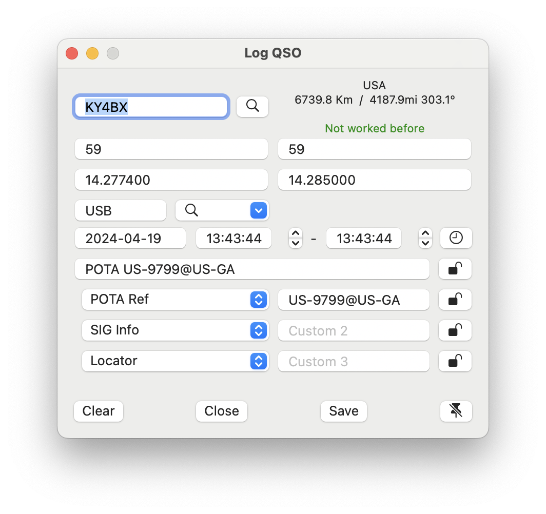
In this view, you can observe the POTA data pre-populated in the logging window. Take note that the Custom fields are activated here (refer to the Logbook chapter for further details on Custom fields).
Note
For FT8 operations and to utilize this feature, ensure both auto-logging settings are deactivated, otherwise FT8 QSOs will be logged without the supplementary POTA information.
22.1. Map
By selecting the MAP button, you can display all current POTA stations on a Map.
1. Modes
Under the Modes menu, you will find tools for operating in certain modes like CW or FT8.
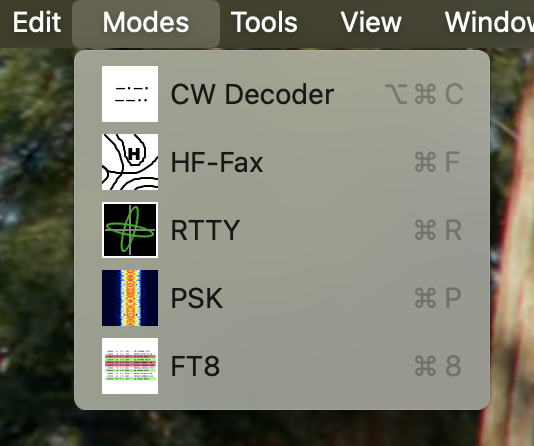
2. CW Decoder
The CW Decoder Tool can be used to decode CW signals.
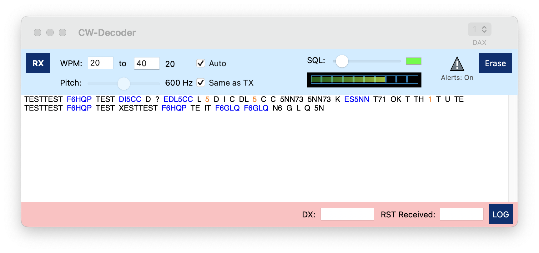
Once you tune to a CW signal and hit the RX button, the tools starts to decode CW signals.
Depending on the noise on the frequency you may see random characters instead of well decoded CW. You can always hit the Erase button to clear the receive section
The CW decoder will try it’s best to identify the speed of the other station which will be displayed at the top. Identifying the speed will require receiving at least two characters so the first characters of a submission might get lost or could be wrong. You can prevent this in case you already know the speed of the other station. In this case, you can uncheck the Auto checkbox and enter enter the expected speed as WPM.
You can also use the SQL-Slider to eliminate the noise characters but this will even make it harder to find the correct speed.
3. HF Fax
This Tool allows to receive, display and store HF Fax or Weather-Fax (WeFax) transmissions often used for submitting weather maps and weather information.
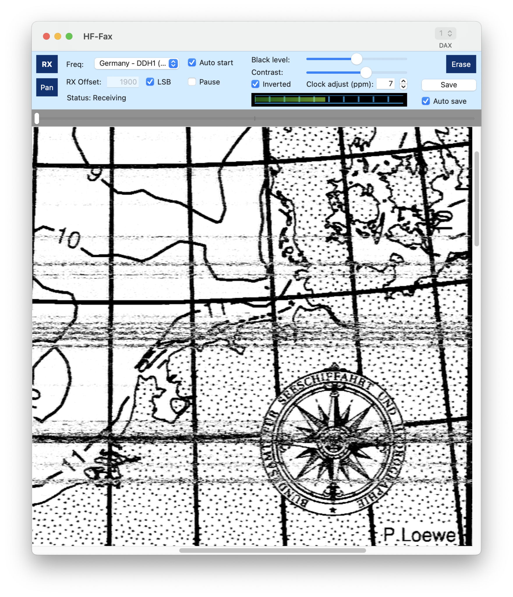
To use this tool, first either tune to the desired frequency manually and select “Manual” for the Freq: selection or select one of the predefined entries of the list.
For these preselected entries, values for RX Offset, LSB and Inverted will be set automatically.
Hitting the RX button will start receiving. If the “Auto Start” checkbox is on, the Tool will wait for the synchronization signal until anything is displayed. Otherwise receiving starts immediate.
Using the slider at the top, you can adjust the image offset if the start of the image has not been detected automatically.
The clock adjust entry can be used to adjust the slant of the image due to a clock inaccuracy.
The Erase button will clear the received image.
The Save button can be used to save the received image as .png file.
If you check the Auto save checkbox, you will be prompted for a directory, where to store all received images separately.
4. SSTV
This tool enables the transmission, reception and storage of Slow-Scan TV (SSTV) images.
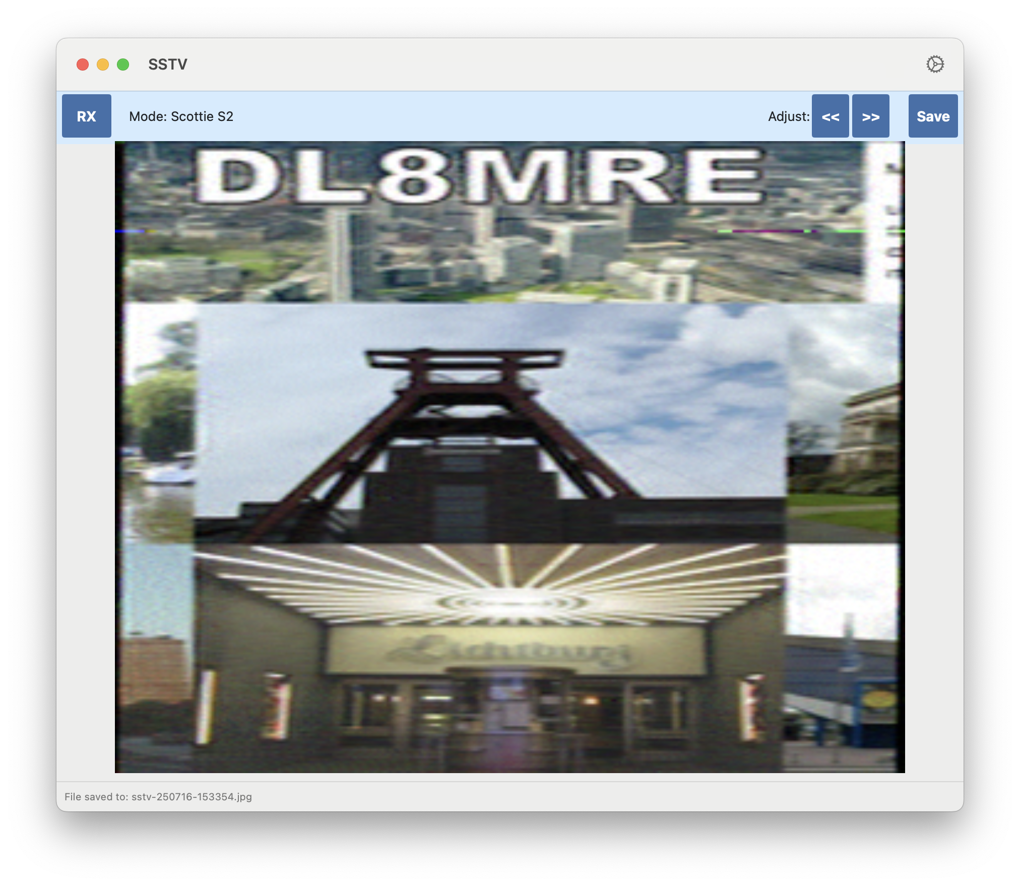
To utilize this tool, tune to a frequency where an SSTV signal is being transmitted.
Hint
The most popular SSTV frequency is 14.230 MHz (USB). Other frequencies include 21.340 MHz (USB), 7.171 and 7.110 MHz (LSB), 3.730 MHz (LSB) in the 10m Band, and 28.680 MHz (USB). Additionally, the International Space Station (ISS) occasionally transmits SSTV on 145.800 MHz (FM).
Change the mode accordingly. It is ideal to select the DATA mode to utilize the maximum filter width.
Pressing the RX button will start the reception process. Once an SSTV header tone is detected, the app tries to automatically identify the mode of the transmission and begins receiving the image, which will be displayed line by line during reception.
Once an image has been fully received, you can adjust the ‘slant’ and offset by using the buttons at the top right side.
The Save button allows you to save the received image as a .jpg file.
To send (transmit) an image, load the image using the Load button, select the desired mode, and hit the TX button.
Hint
Martin M1 and Scottie S1 are the most popular and provide good quality. For quick submissions, try M4, which offers very low quality but doesn’t take very long.
Note
You can add an individual text to the image once it was loaded using the Watermark button at the top. The text can also contain variables such as {CALL} or {RECRST} which will be replaced before the picture will be transmitted. For a list of variables, please see chapter Macro Variables further below in the manual.
It is common to use your own call-sign as FSK ID, which will be transmitted at the end of the SSTV image transmission. For this, your call-sign is pre-populated in the My ID field. Once a picture has been received and a FSK ID was detected, it will be transferred to the His ID field.
Hitting the Log button will open the Logbook entry screen with Mode (SSTV), Frequencies, and FSK ID pre-populated.
In the Settings, you can enable the Autosave feature, which automatically saves all received images to the Mac’s Downloads folder.
The following SSTV formats are supported:
Name |
Size and Color |
Martin M1 |
320 x 256 GBR |
Martin M2 |
320 x 256 GBR |
Martin M3 |
320 x 128 GBR |
Martin M4 |
320 x 128 GBR |
Scottie S1 |
320 x 256 GBR |
Scottie S2 |
320 x 256 GBR |
Scottie DX |
320 x 256 GBR |
Robot 72 |
320 x 240 YUV |
Robot 36 |
320 x 240 YUV |
Robot 24 |
320 x 240 YUV |
Robot 24 B/W |
320 x 240 BW |
Robot 12 B/W |
320 x 120 BW |
Robot 8 B/W |
320 x 120 BW |
Pasokon P3 |
640 x 496 RGB |
Pasokon P5 |
640 x 496 RGB |
Pasokon P7 |
640 x 496 RGB |
PD-50 |
320 x 256 YUV |
PD-90 |
320 x 256 YUV |
PD-120 |
640 x 496 YUV |
PD-160 |
512 x 400 YUV |
PD-180 |
640 x 496 YUV |
PD-240 |
640 x 496 YUV |
PD-290 |
800 x 616 YUV |
Wraase SC-2 120 |
320 x 256 RGB |
Wraase SC-2 180 |
320 x 256 RGB |
5. RTTY
The App integrates an RTTY decoder/encoder to facilitate operation in RTTY mode.
Due to the limitations of the Icom RTTY Mode, the App does not utilize the transceiver’s native RTTY functions. Instead, it implements its own RTTY encoder and decoder, which often outperforms the built-in decoder.
Selecting RTTY from the Modes menu will bring up the RTTY main screen.
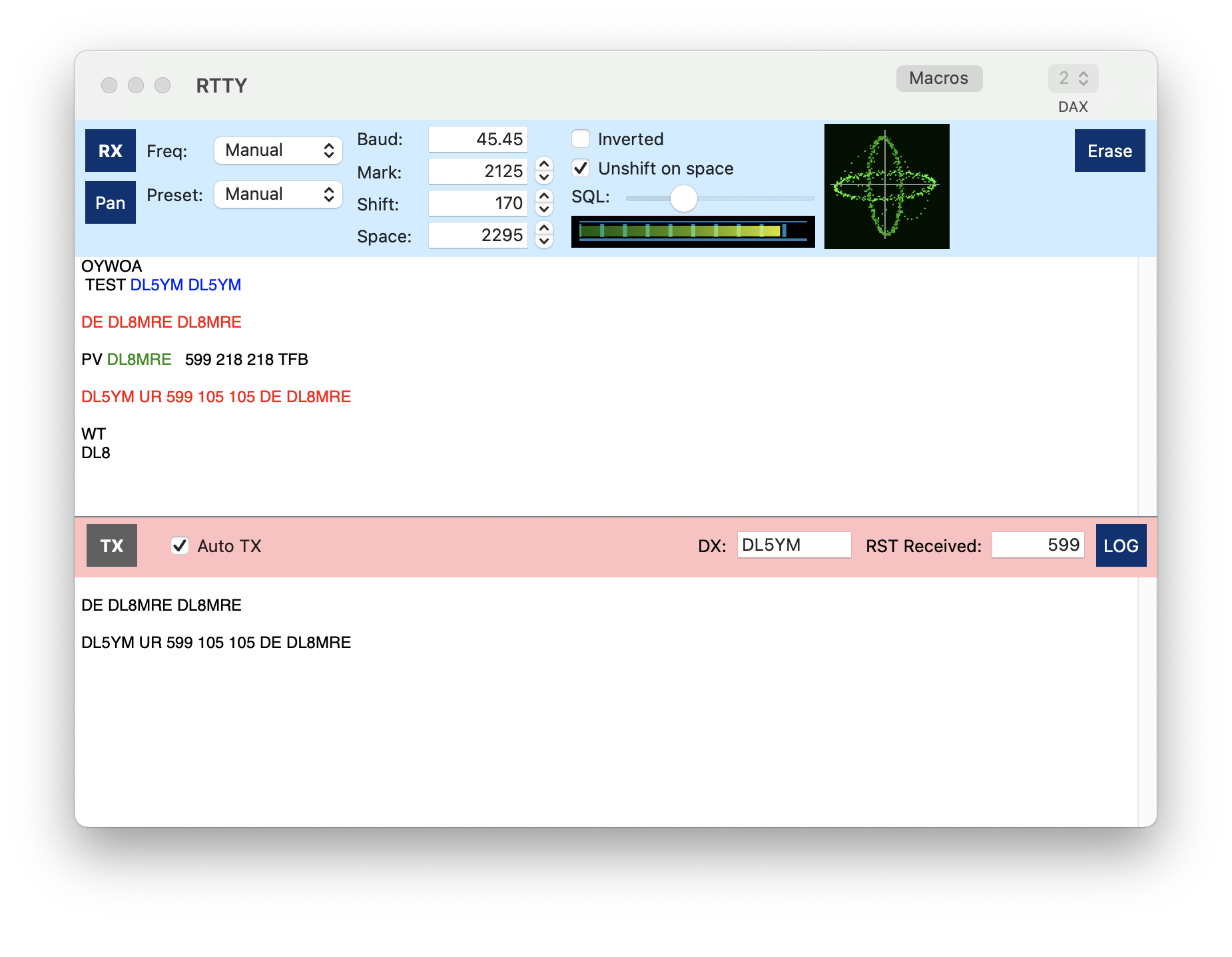
5.1. Upper blue RX part
In the upper (blue) RX section of this screen, you can adjust all parameters for RTTY operation. Incoming text will be displayed below.
The Freq and Preset options are provided for convenience. The Freq selection switches to a specific band segment commonly used for RTTY and adjusts all necessary settings for RTTY operation. This list includes frequencies of known Weather stations that transmit in RTTY. The Preset selection offers a list of common Mark/Shift and Baud settings. Alternatively, you can manually tune to the desired frequency or adjust the Baud rate as needed.
Clicking the RX button initiates the reception process. The RTTY tool always uses the left main VFO. Once engaged, additional parameters like mode, mark, and space frequency will be set automatically.
Below the blue area, all received characters will be displayed.
5.2. Lower red TX part
By clicking on the TX button, text entered into the Text field will be transmitted. Alternatively, selecting the Live checkbox will start transmission shortly after typing begins and will end automatically when typing ceases.
5.3. Operating in RTTY
After tuning to the desired RTTY frequency using the regular frequency tuning methods and clicking the RX button, all incoming text will be displayed. Note that weak signals may result in some garbled text.
To tune into another RTTY signal, you’ll notice two yellow lines on the waterfall representing the Mark and Space frequencies. These lines must align with the corresponding lines of the target signal on the waterfall. For precise tuning, use the scope feature of the RTTY tool. The ellipses should resemble those shown in the screenshot above.
When a call sign is received, it will appear in a distinct color. A blue color signifies a new contact. Call signs already logged will show in gray. Your own call sign will appear in green.
Clicking on a colored call sign will transfer it to the DX: field for logging and macro usage (see below). Right-clicking a call sign provides additional information such as country, DX, ITU-Zone, etc.
Text that has been transmitted will also be displayed in red.
Pressing the LOG button will open the Log Entry view to record your RTTY QSO.
To clear the entered text, click the Erase button at the top once for the lower TX field. Double-clicking the Erase button will clear the RX section as well.
5.4. Using Macros
You can maintain separate RTTY Macros by clicking the Macros button at the top of the RTTY screen.
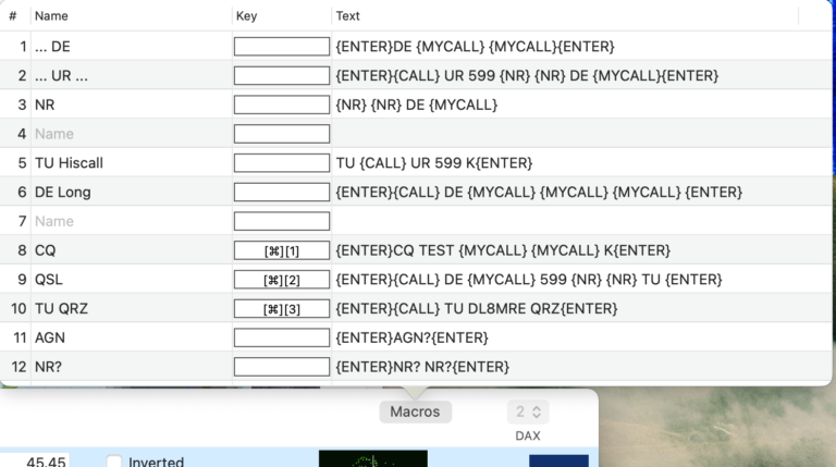
From here, similar to CW or Voice Macros, you can maintain a Macro title, a hotkey and the text which should be sent if the Macro is called.
To uses these Macros, just use the View → Macros Menu to display the Macros panel. This panel always displays the right Macros (CW-, Voice-, RTTY) for the mode of the currently active slice.
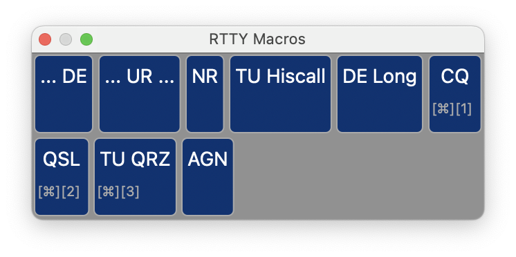
Like for CW or Text-To-Speech Voice Macros, also RTTY Macros can use variables like {CALL} which are replaced before being sent.
If you either hit the hot-key (if maintained) or click the button, the Macro text with possible substitutions of the variables will be added to the Text entry below the red TX area just as if you would have typed in this text. This text will get sent, once you hit the TX button or immediately if you have checked the Auto TX checkbox.
You can also right-click a Macro button to see, what would actually be sent in case you don’t remember exactly what’s behind a certain Macro or to see how variables will be substituted.
6. PSK
The App integrates a PSK decoder / encoder to operate in one of the six supported PSK modes.
Selecting PSK from the tools menu will display the PSK main screen…
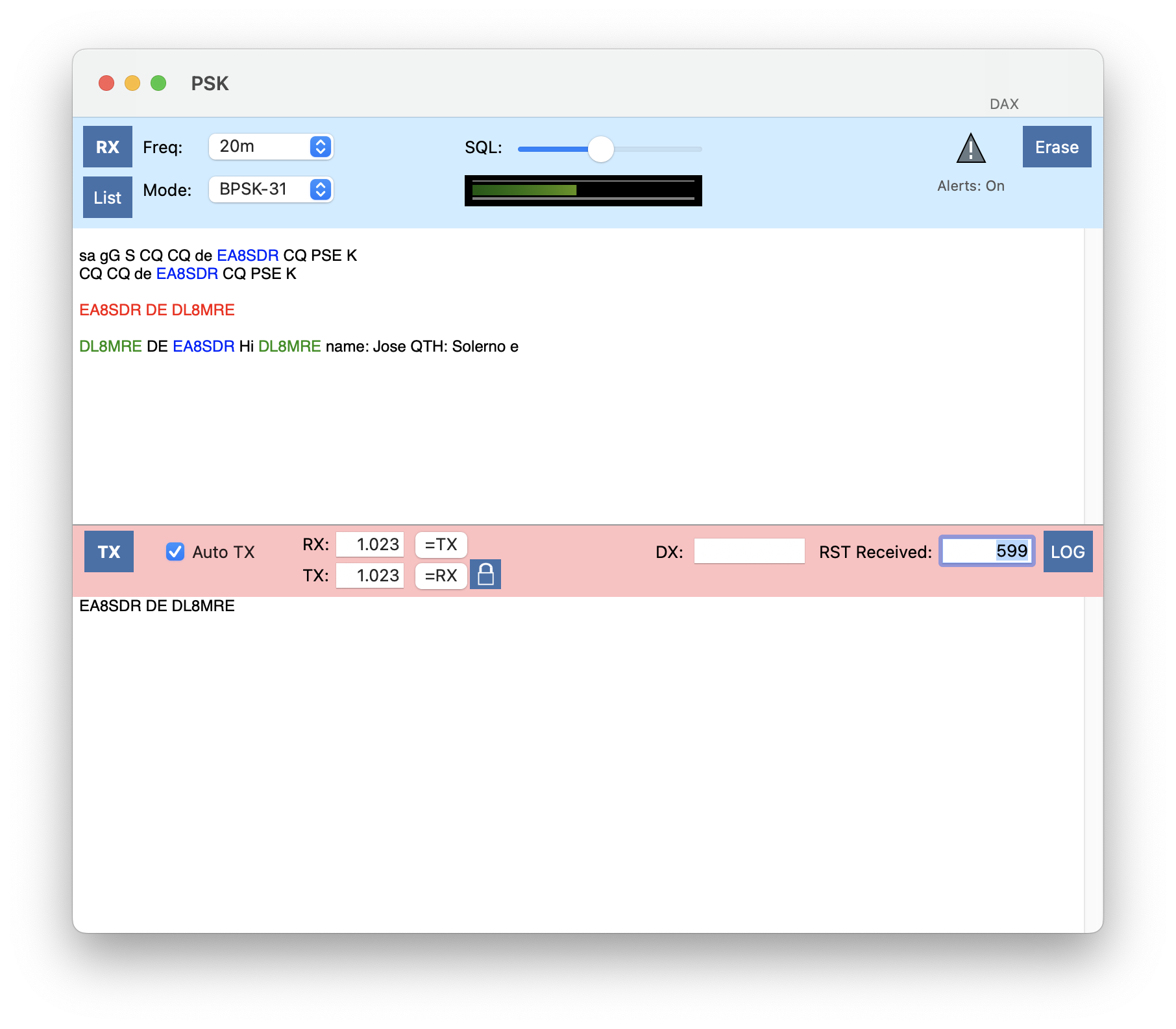
…and the PSK RX List window.
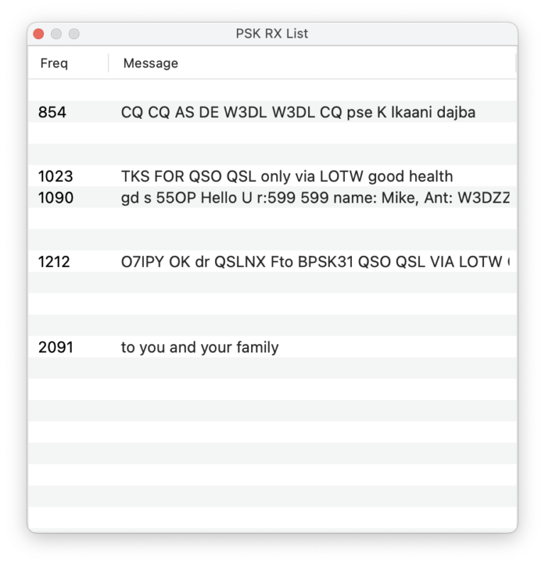
6.1. Operating in PSK
To start operating in PSK, first select the desired Frequency/Band using the Freq: selection. This way, the Radio will be tuned to the common frequencies that are usually used for PSK. If you want to operate on a different frequency, just select “Manual” and tune the VFO to the desired frequency.
In the Mode: selection, you can chose which of the six PSK modes you like to use. The most common mode is “BPSK-31”.
Once you hit the RX button, decoding will start and if signals were found, they will be listed in the separate PSK RX List window as shown above.
This list contains all current decoding of the complete filter spectrum. Decodings are ordered by frequency. The PSK frequency is displayed in the left column and a brief summary of the decoding on the right.
You can now pick one frequency by clicking on a line in the list. The line will then be displayed highlighted in red and the PSK main window will take over the PSK frequencies in the RX and TX fields. Also, the main window will start decoding.
Decoded call-signs will be highlighted like in the other FT8 or RTTY tools. You can click on a call to take it over to the DX field. This way, it is easier to use variables like {CALL} in PSK Macros for answering calls.
By clicking on the TX button, everything that has been entered in the lower text area will be transmitted. Instead of using the TX button, you can also check the Auto TX checkbox. In this case, transmission will begin shortly after something has been typed and will automatically end if you stop typing.
Like RTTY, PSK makes much sense in combination with Macros. As mentioned before, you can maintain PSK Macros and use variables. The Attachment of this manual contains a list of available Variables.
To log a QSO, you can just hit the LOG button. Several fields, including the DX callsign, will be prepopulated so you just have to click on “Save QSO” to add the new entry to your Logbook.
For calling CQ yourself, you won’t click on a line of the PSK RX List but instead enter the desired PSK frequency manually in the TX: field.
Using the SQL Slider, you can mute PSK decoding of noise. Just increase the slider until you don’t see any erratic characters of being decoded. Keep in mind that using this Squelch option may cause a few first characters to get lost.
You can enable/disable Alerts by clicking the Alerts Icon at the top. To maintain your Alerts use the Alerts Tool under the Tools menu. Alerts will ring for each call occurring in the PSK RX List.
7. APRS
This tool allows you to receive and send APRS packets.
7.1. What is APRS?
APRS stands for Automatic Packet Reporting System. It is a digital communication protocol used by amateur radio operators to exchange real-time information such as:
Position reports (GPS locations)
Short messages
Status updates
Weather data
Telemetry
Object information (such as repeaters, events, or hazards)
Unlike traditional voice QSOs, APRS packets are sent automatically and can be received by any station listening on the APRS frequency. Many APRS stations are connected to the APRS-IS (Internet System), allowing global exchange of messages and positions through gateways (iGates).
Tip
APRS is not just about position tracking. It is a versatile system that supports tactical communication, situational awareness, and even integration with email or SMS services in certain regions.
Before using the APRS tool, configure your APRS call sign in the settings of this tool. See the chapter APRS Settings further below for details.
To use this APRS tool:
Tune your radio to the correct APRS frequency for your region.
Set the mode according to the regional standard (usually FM).
Select a wide filter so the full APRS signal can be decoded.
Common VHF APRS frequencies by region:
North America: 144.390 MHz (FM)
Europe: 144.800 MHz (FM)
Oceania (Australia, New Zealand): 145.175 MHz (FM)
Japan: 144.660 MHz (FM)
South America: 145.570 MHz (FM)
Note
APRS operates on narrowband FM, but always use a wide enough filter so the full packet (1200 baud AFSK) can be received.
Operating APRS frequencies on HF:
40m 7.0486 MHz LSB
30m 10.1476 MHz USB
20m 14.103 MHz LSB
Note
For operating on HF select 300 baud AFSK under Settings.
Common HF
Once you hit the RX button in the top left corner, the tool will start receiving APRS packets and display them in a list, with the newest packet at the top.
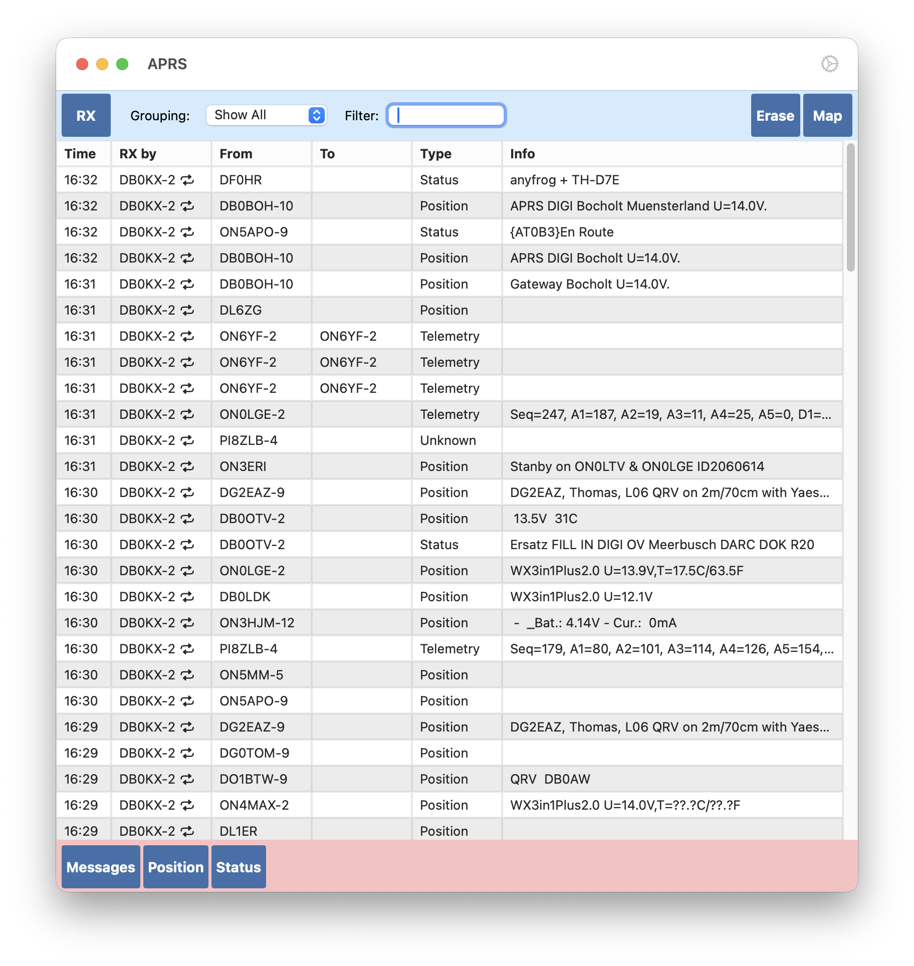
7.2. The RX Packet List
The RX Packet List shows all received APRS packets in a table.
RX by – The call sign of the station that relayed or transmitted the packet to you.
From – The originating call sign of the packet.
To – The destination call sign. Only filled for certain packet types (e.g., messages, telemetry).
Type – The type of APRS packet: Message, Position, Status, Telemetry, Capabilities, Object, or Unknown.
Info – A brief summary of the packet contents.
You can click on any entry to view more detailed information about that packet.
7.2.1. Filtering and Grouping
As the list grows large, you can:
Group the list by Sender, Source, Destination, or Message type.
Filter packets by entering search terms. The filter searches across all columns.
Examples:
Entering DL8MRE-7,DL8MRE-8 shows all packets containing either call sign.
Entering -Status shows all packets except Status messages.
Using * matches everything.
Hint
You can combine filters with commas and use - to exclude. For example: *,-Telemetry shows all packets except telemetry.
Hitting Erase clears the list. Additionally, packets will automatically expire after a configurable time (see APRS Settings).
7.2.2. Mapping
Clicking the Map button displays all packets containing positions on a map. This can show fixed locations or moving stations/routes.
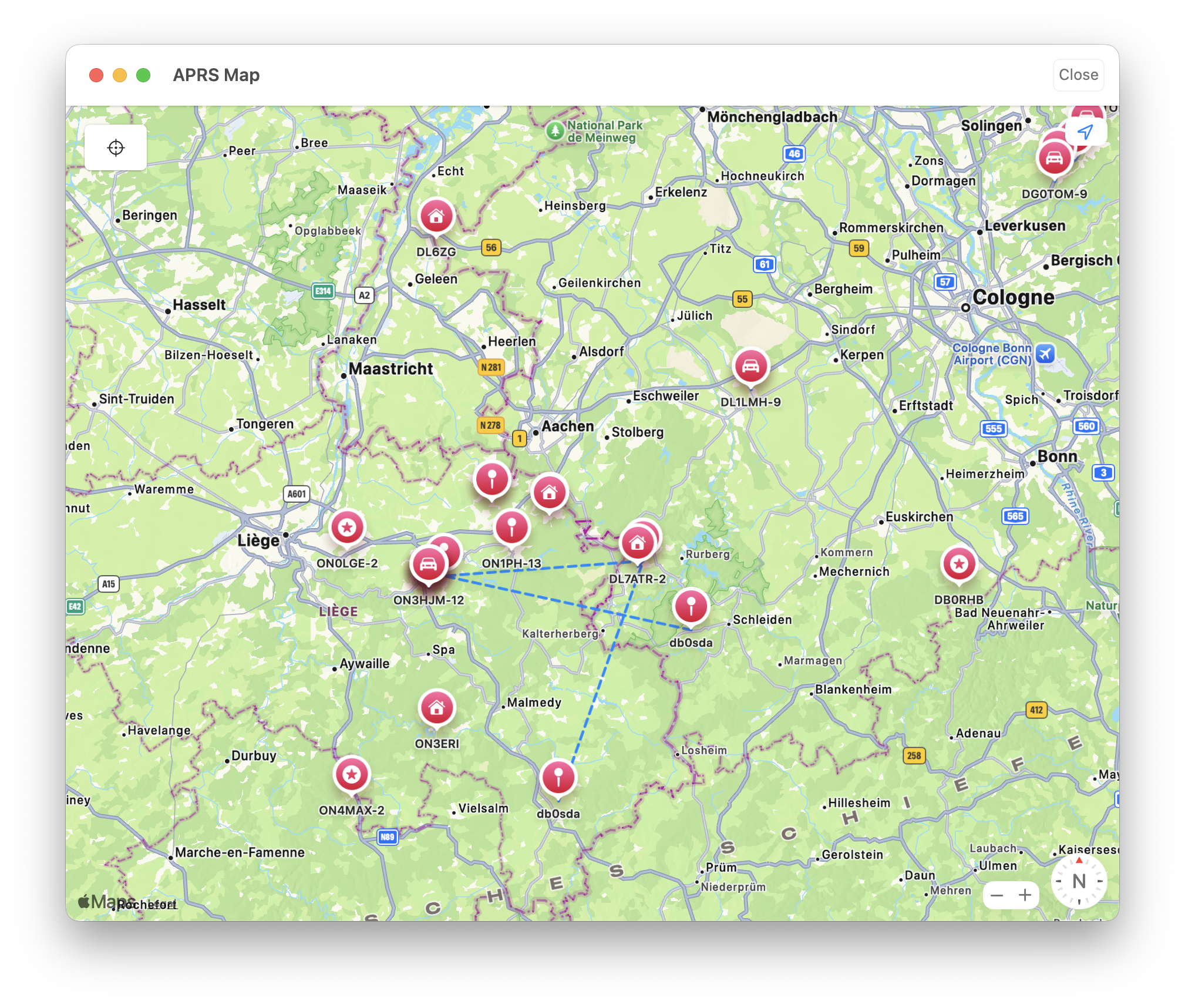
7.3. Transmitting APRS Packets
This tool allows you to transmit APRS Messages, Positions, and Status reports.
Important
Set your radio squelch correctly before transmitting. - Squelch should remain closed when no signal is present. - It should open immediately when a signal is received. APRS will not transmit while another signal is present, preventing collisions on the channel.
Clicking the Messages button opens the APRS Message view.
Use Messages or Bulletins tabs at the top to switch modes.
Use Received or Sent tabs to switch between inbox and outbox.
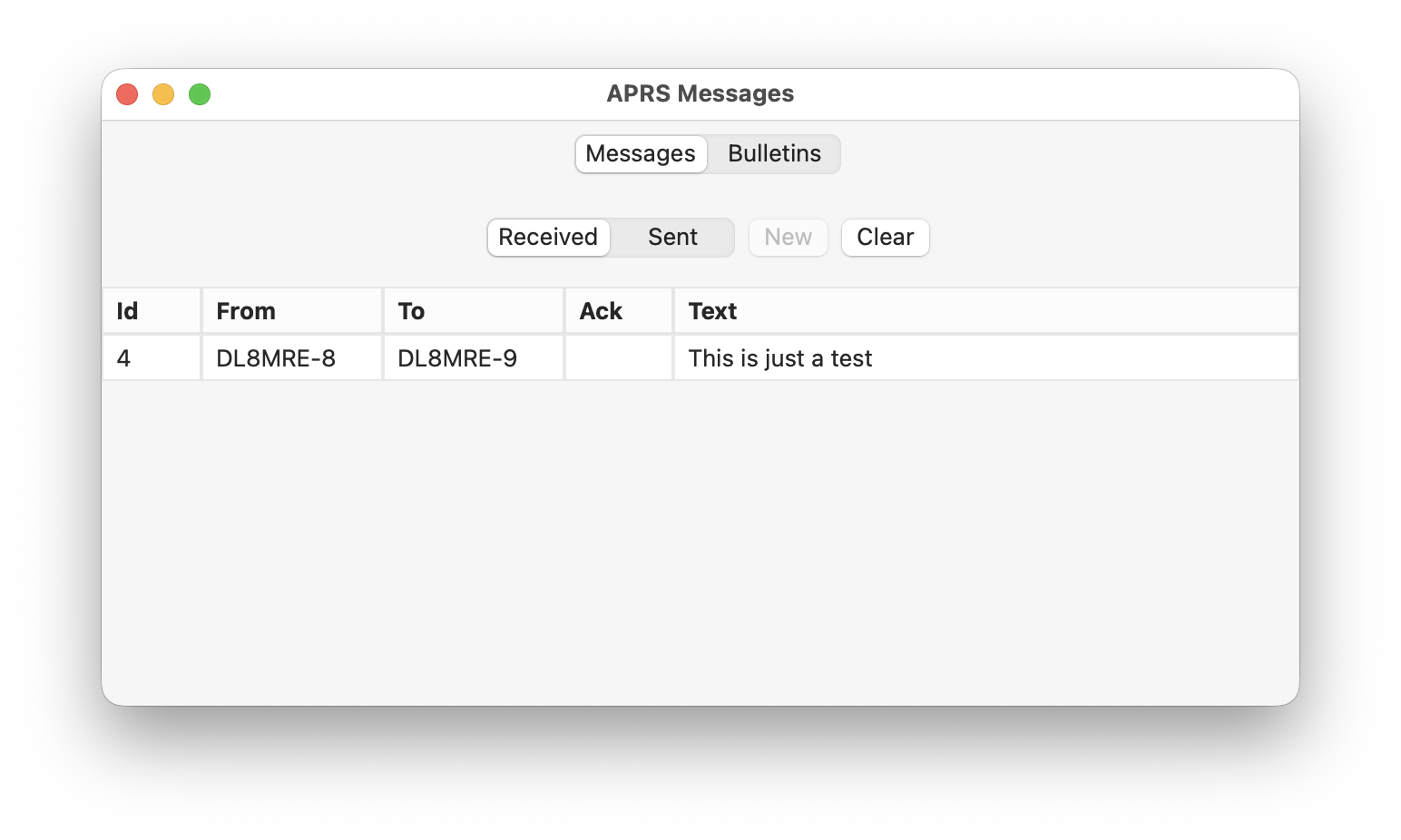
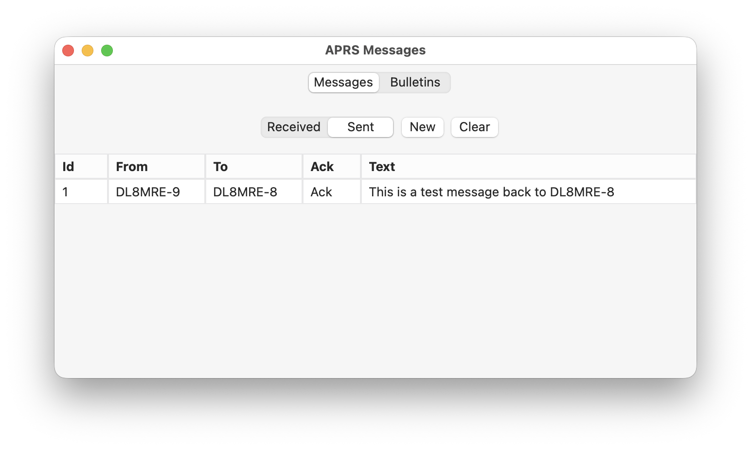
To compose a new message, go to Sent (Outbox) and press New.
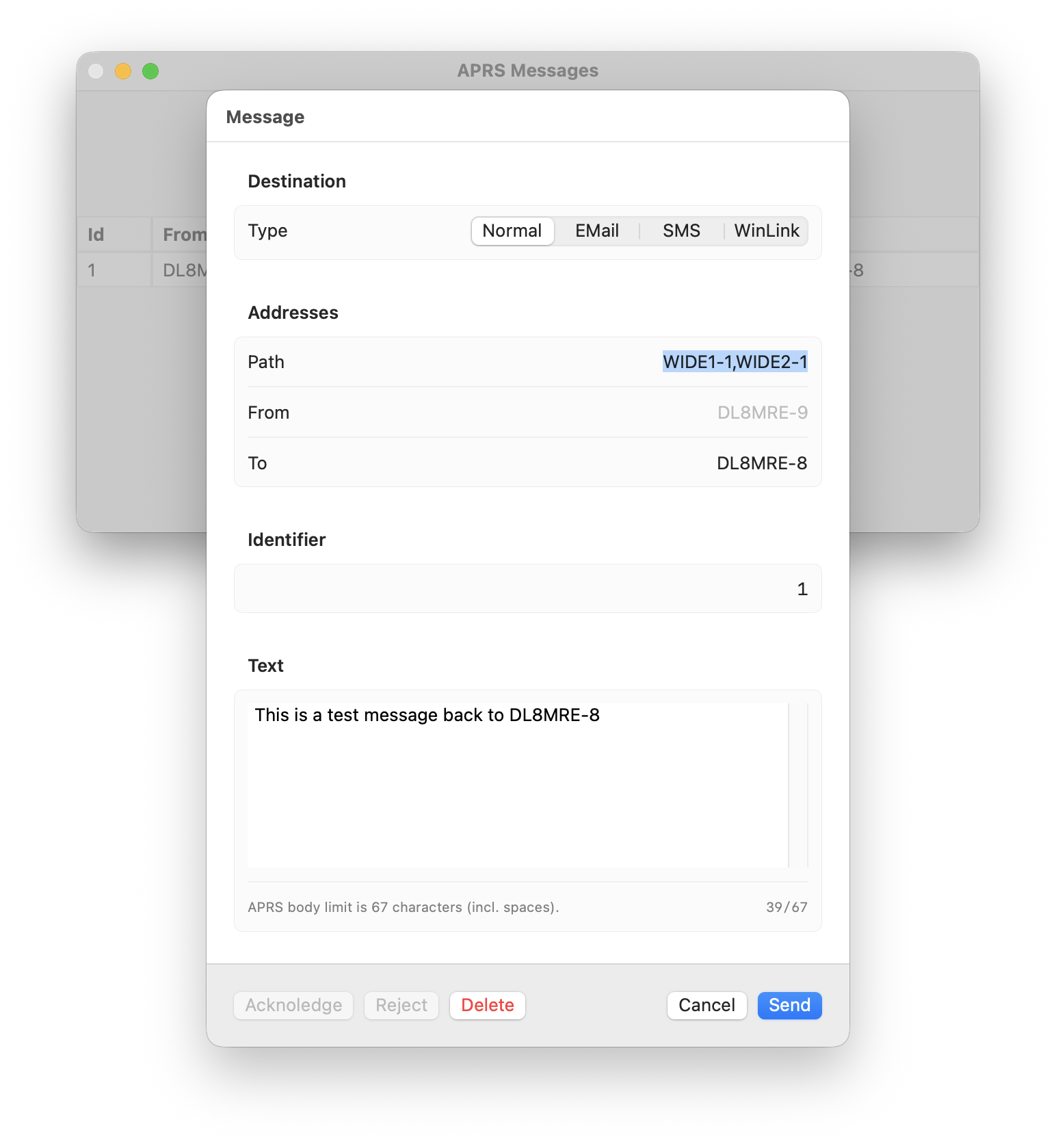
Available message types:
Normal – Standard text message to another station.
EMail – Send an email (if supported in your region).
SMS – Send a text message to a mobile phone (if supported).
WinLink – Send a message via the WinLink system.
Important
APRS messages are sent in plain text, unencrypted. Anyone monitoring APRS can read them. If you include email addresses or phone numbers, they will be public.
Note
Not all regions support EMail, SMS, or WinLink services. Check local availability.
Message limitations:
Maximum length: 67 characters.
Each message has an auto-incrementing identifier number.
Acknowledgments (ACKs) may or may not be sent by the receiving station.
Tip
If your message is not acknowledged, open the message in your Outbox and press Send again to retransmit.
Example: A received message displayed on a Kenwood TH-D74:
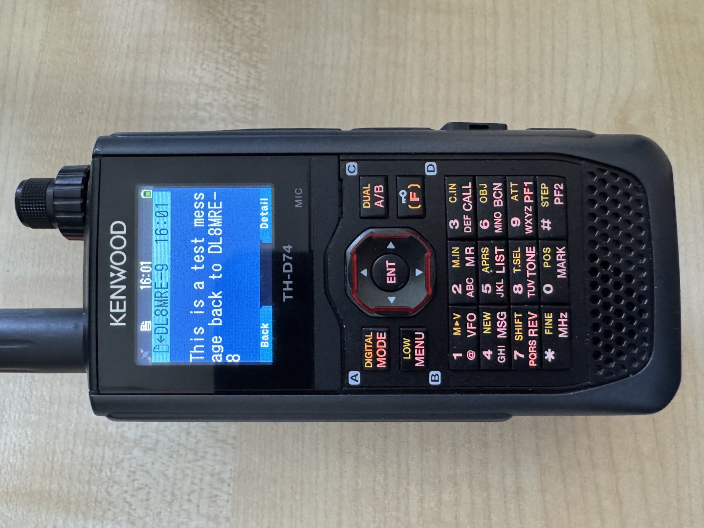
In addition to Normal, Email, and SMS, you can send and receive WinLink messages.
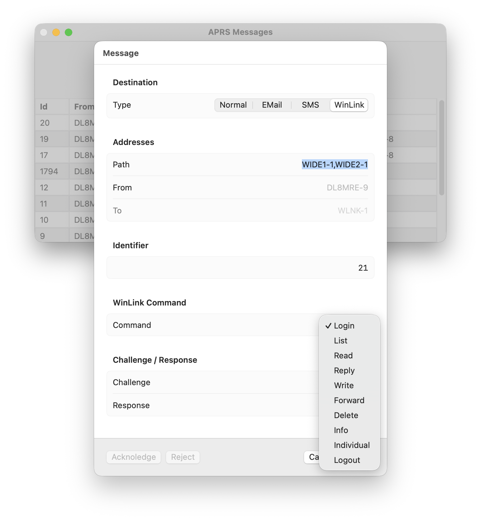
Available commands: Read, Reply, Write, Delete, Forward, List, Logout.
7.3.1. WinLink Login Procedure
Before sending WinLink messages, you must log in:
Send any WinLink command (e.g., List).
WinLink will respond with a login challenge such as: Login [593]: Here 593 refers to the 5th, 9th, and 3rd characters of your WinLink password.
You must respond with those three password characters, plus three random characters, in random order. Example: Password = secretpassword, challenge [593] → response contains e, s, c plus three random characters.
Important
Never send your full password. Only the challenge/response mechanism is used.
This tool can handle the login challenge automatically if you enter your WinLink password in the APRS Settings.
After successful login, you will receive a Welcome message and can proceed with other commands.
Note
Responses from WinLink may take time. Be patient, and retransmit messages manually if needed.
7.3.1.1. Sending Positions
Click the Positions button to transmit your location.
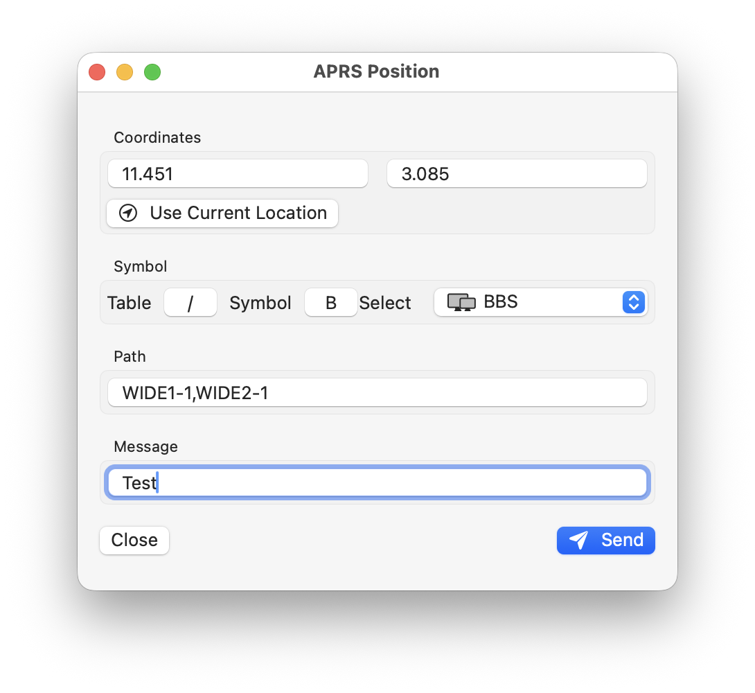
Example of a received position report:
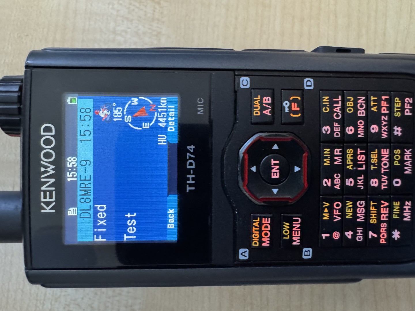
7.3.1.2. Sending a Status Report
Click the Status button to send a short status message.
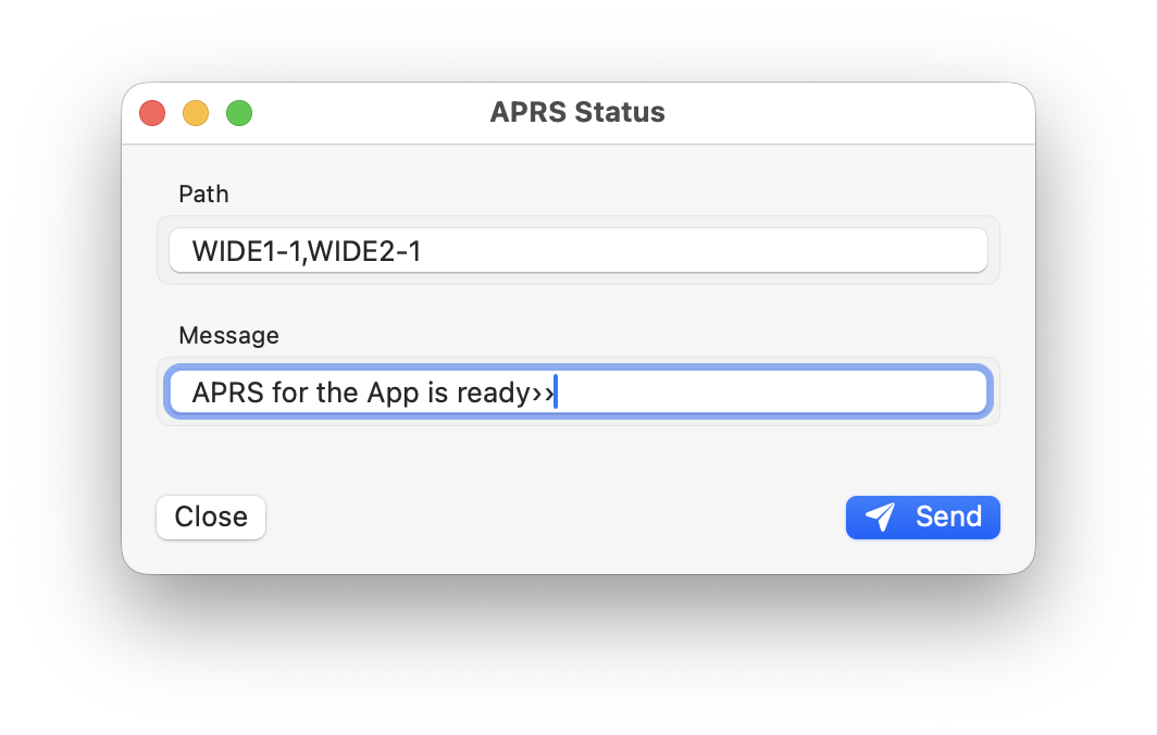
Example of a received status message:
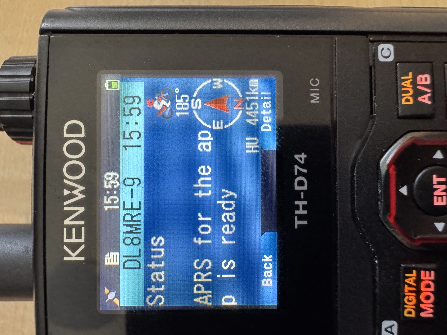
7.4. APRS Settings
Click the gear icon at the top to open APRS tool settings.
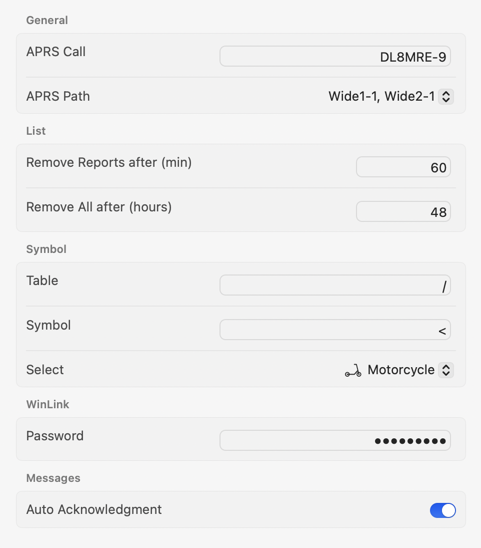
Available settings:
APRS Call Sign – Enter your call sign with SSID (e.g., DL8MRE-7).
APRS Mode – 1200 Baud (e.g. for VHF/UHF) or 300 (for HF).
APRS Path – Common default: WIDE1-1, WIDE2-1.
Packet Expiry – Choose how long packets remain in the RX list.
Default Symbol – Select the symbol for your position reports. .. note:: Only the standard / symbol table is supported in the picker. For other tables, enter symbol codes manually.
WinLink Password – Required if using the automatic challenge/response login.
Auto Acknowledgement – If enabled, incoming APRS messages are acknowledged automatically.
Tip
Using Auto ACK ensures better reliability, but you can also manage acknowledgments manually from the Messages Inbox.
8. WSPR
This tool allows you to receive and send WSPR packets.
8.1. What is WSPR?
WSPR (Weak Signal Propagation Reporter) is a digital radio mode used by HAMs to study how radio signals travel around the world.
WSPR usually uses low transmit power (often milliwatts) and highly sensitive decoding to detect signals over long distances. Stations automatically transmit short beacons containing their callsign, grid locator, and power level. Other stations receive and decode these signals and upload reception reports (“spots”) to a public database called WSPRnet available on https://wsprnet.org .
By collecting thousands of these reports, WSPR makes it possible to:
Observe real-world radio propagation in near-real time
Compare band performance by time of day and season
Experiment with antennas, locations, and ultra-low-power operation
In short, WSPR turns many simple radio beacons into a global, crowdsourced propagation experiment.
A WSPR packet starts at an even minute boundary (00 seconds) and lasts 110 seconds.
8.2. Using the WSPR Tool
Like most tools in this app, the WSPR tool features a blue section at the top dedicated to receiving, while the lower part, marked with a red heading, focuses on transmission.
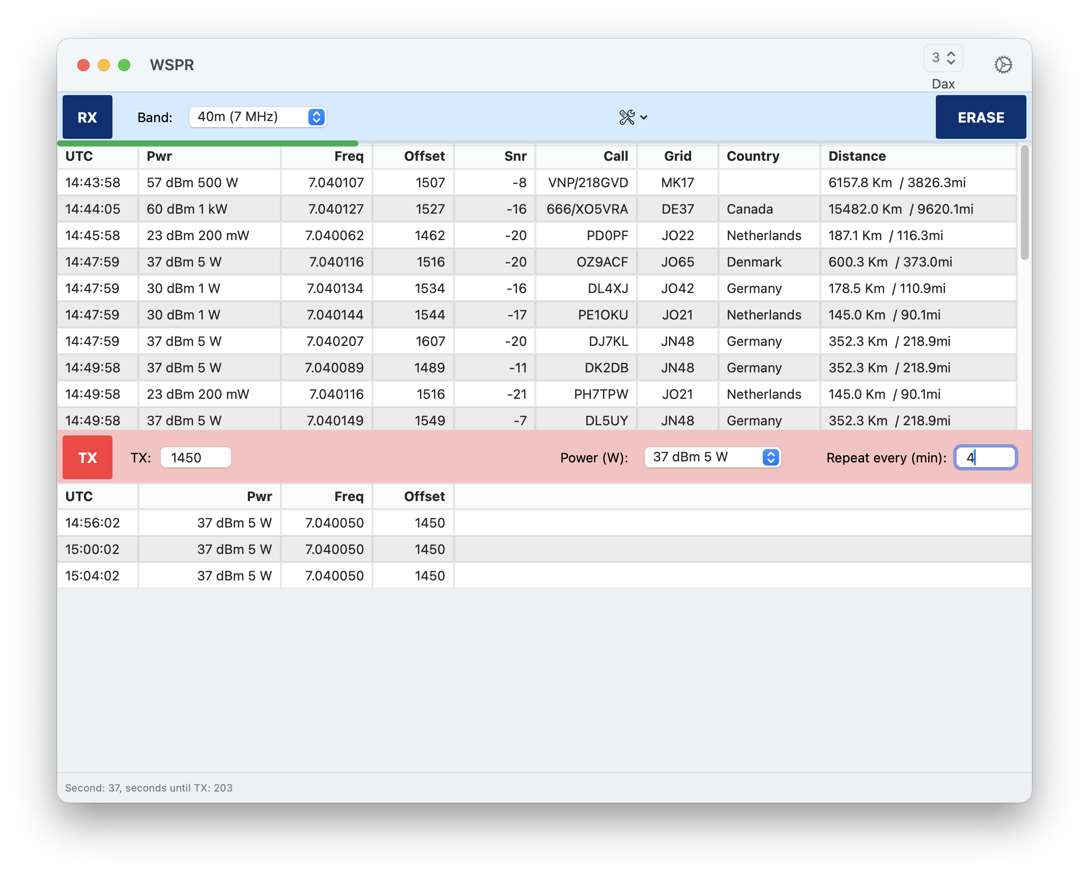
To begin operating in WSPR mode, first select a band. This action automatically tunes the radio to the standard WSPR frequency for that band.
Next, press the RX button to start receiving WSPR signals.
After a short period, you will start seeing incoming WSPR packets.
To transmit your own WSPR packets, choose a TX frequency offset within the range of 1400 to 1600 Hz. It’s best to avoid the center frequency of 1500 Hz, as it is commonly used by others. Set the power level you wish to report, and choose the Repeat time, which is the interval in minutes at which your packets will be sent.
Note
The power level setting here does not reflect the actual power setting of your radio.
Finally, press the TX button to initiate transmission. When the time for the next packet arrives, the transmission will commence and will continue at subsequent intervals as set.
9. FT8
This tool enables HAM Radio operators to utilize and operate the popular digital modes FT8 and FT4, which were invented by Nobel Prize laureate Joe Taylor, K1JT.
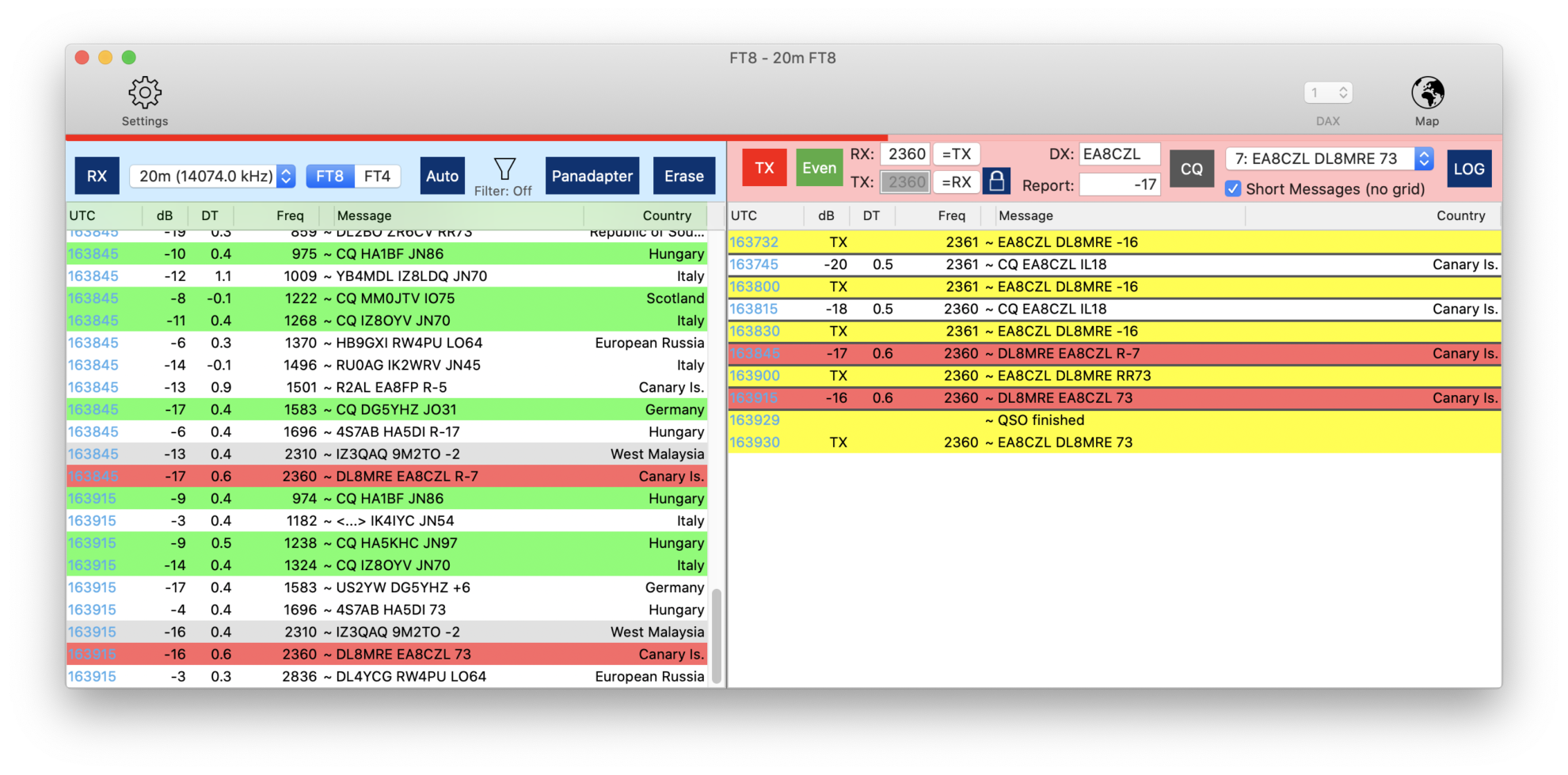
The screen above shows a typical FT8 QSO.
9.1. Foreword (please read)
I had the pleasure of meeting Joe in Dayton in 2019. His lecture was the catalyst for me to prioritize the integration of this feature into my SmartSDR iOS App. Grasping his method for encoding and decoding FT8 messages was a learning curve, involving a deep dive into FFT (fast Fourier transformation). I’m proud to say that all my Apps now boasts a comprehensive FT8/FT4 Tool.
We owe a debt of gratitude to Joe Taylor , the architect of this exceptional mode.
9.2. Requirements / Features
This App seamlessly supports both FT8 and FT4 modes. While Contest/DX-Pedition mode isn’t natively supported, you can still engage in hound mode to pursue DX-Peditions (for a detailed guide on this, refer to the section below).
The App features an AUTO mode for the automated generation of response messages upon receiving communications. It also includes Auto Logging to effortlessly record every QSO without manual input. To help avoid duplicate contacts, “Worked before” Calls are highlighted, and CQ Calls are visibly represented on the Waterfall akin to DX-Cluster Spots. Utilize Filters to refine the list and display only the stations of interest.
9.3. How to use
My objective was to provide an FT8 experience that requires minimal configuration and operational effort. Users acquainted with WSJT-X will find the transition to using FT8 within this App seamless. If you are new to FT8 or previously found it daunting, the essential instructions below will equip you for your initial QSO.
I aspire to inspire more HAMs to explore this innovative mode of communication by offering a user-friendly and straightforward FT8 tool. If FT8 seemed too complex before, I encourage you to give it a shot with this App. Say goodbye to the hassle of cable connections, audio interfaces, obscure settings, or CAT commands.
Simply launch the tool and embark on your first FT8 QSO.
9.4. A few FT8 Basics
A typical FT8 QSO starts by somebody (say K1CQ) calling CQ, next somebody like you (say DC1ME) is answering. Both will then exchange their signal reports and optionally end the QSO by saying 73.
Here is how it typically looks like:
Caller |
You |
Meaning |
|---|---|---|
CQ K1CQ EN61 |
K1CQ is Calling CQ. His Grid locator is EN61 |
|
K1CQ DC1ME JO12 |
You are replying to him with your Grid locator |
|
DC1ME K1CQ -11 |
K1CQ responds to you with a signal report |
|
K1CQ DC1ME R-10 |
You, confirming his report and send your own report |
Now, there are two typical options:
Option 1 (the fastest and more common):
DC1ME K1CQ RR73 |
K1CQ confirmed the reception of your report and says best regards. The QSO is done now. No need to respond again |
Option 2 (more polite option which takes longer):
CDC1ME K1CQ RRR |
K1CQ confirmed the reception of your report |
|
K1CQ DC1ME 73 |
You say best regards |
|
DC1ME K1CQ 73 |
K1CQ send his best regards and the QSO is over |
If you would like to call CQ yourself instead, the procedure is the same. Just swap the Callsigns in the above table.
These so-called FT8 messages cannot be longer than 13 Characters. It takes 13 seconds to transfer these messages and they will be exchanged every 15 seconds. Thus, there can be 4 messages per minute. When sending at second zero or 30 it is called “even” or “first”. When sending at second 15 or 45, it is called “odd”.
Besides these aforementioned typical QSO messages, there is additional information that will be added to messages in Contests Mode or DXpedition mode. These modes are not supported by this FT8 tool.
CQ Callers may also add either DX or the desired destination to their CQ message if they just want to get an answer from certain stations.
For example:
CQ DX K1CQ EN61 |
K1CQ just wants to have DX QSOs |
CQ JA K1CQ EN61 |
K1CQ just want to have contact with Japan |
And that’s pretty much it. That’s all you need to know to operate in FT8 with this App.
If you want to learn more, just head to G4IFBs website which includes a fantastic FT8 Operating guide, written by Gary Hinson, ZL2IFB : www.g4ifb.com which is also available in other languages.
Note
Some users asked why my app waits another cycle or even sends another 73 message after previously sending a RR73 message. A RR73 message usually ends the QSO, but it turned out that some FT8 implementations simply ignore this. It can also happen that the RR73 was not received on the other end, causing the other station to send an unnecessary extra 73 message. In the past I was simply ignoring this extra 73, but it turned out that in many cases the QSO didn’t get logged on the other side, which is why my app now waits another cycle and, if it correctly receives an additional 73, it also responds with a 73 to that message. So my app favors reliable QSO logging over QSO speed.
9.5. Using the FT8 tool
You can start the FT8 Tool from the Tools menu as usual.
There are two window parts, the Receive window with the blue header and the Transmit window with the red header. Both are explained more in details below.
9.6. Quick start
If you can’t wait and have no time to read further, the following sequence will perform a quick FT8 qso:
Select a Frequency (next of the RX Button)
Hit the RX button and wait until the list fills
Double-click on any of the entries of the list
… and wait, the whole QSO will be completed automatically even including to have your QSO logged
… if all goes well of course. But there can be situations where something goes wrong or you want to call CQ yourself. The following chapters will describe everything more in detail.
9.7. The Receive Window
On the top half (or left side, if you have switched the flip view setting) you will see the RX window with the blue header.
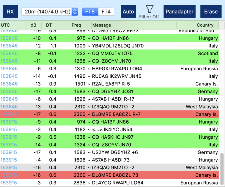
All received messages are displayed on this part of the screen. The following colors are being used:
Green background: Somebody is calling CQ
Gray background: You already worked that station
Red background: your call-sign appears in that message (or you are in TX mode and message was sent on your TX frequency)
9.7.2. The Frequency selection
If you click on the Frequency selection next to the RX button, you can select the Band or Frequency you want to operate. These Frequencies are fixed and you should only operate on these predefined frequencies.
Note
The frequencies may differ depending on your location so please ensure that you set the correct IARU Region in the Preferences for the location from where you want to operate. Please also ensure that you did set your Callsign and your Grid (QTH) locator in the App Settings.
Hint
If you want to operate on another, not supported Frequency, for example to work DX-Pedition stations, you can always select Manual to tune to any frequency.
Once you hit RX, the Radio will not just tune to the right frequency. Also, all necessary parameters such as Mode, Filter width etc. will be set automatically. So should you accidentally have changed some settings, just tap the RX button twice to get the right settings back.
After at least 15 seconds, you may see the first FT8 conversations in the upper receiving part of the screen.
9.7.3. FT8 / FT4
Use these buttons to switch between FT8 and FT4
9.7.4. AUTO
Since QSOs are standardized in FT8 (with the exception of the two options to conclude a QSO, either with “RRR” or “RR73”), automating FT8 QSOs is feasible.
Upon receiving a message, the app is programmed to know which response should be transmitted next.
By activating the AUTO button at the top (turning it blue), the app will automatically choose the correct follow-up message based on the received communication (this applies to both “RRR” and “RR73” scenarios) and will transmit the selected message automatically during the next transmission window.
For additional control or to resolve an interrupted QSO, simply disable the AUTO feature and manually select the desired response.
When Message 9 {Individual} is chosen, you have the flexibility to type and send a custom message that you wish to communicate.
9.7.5. Filter
On a busy frequency, the receive list can quickly become cluttered, potentially causing you to overlook some noteworthy calls. The App includes a filter function, which will be elaborated on later, to help manage the calls displayed on your list. Tapping the Filter Icon opens the filter settings, where you can instantly activate or deactivate the filter, affecting the list displayed below.
9.7.6. Erase
Pressing the Erase button once will clear the contents of the TX Window (further details provided below) and reset all QSO data fields such as DX and Report. Double-clicking the button will additionally clear the RX Window.
This Button is particularly useful for resetting the interface after completing a QSO.
9.7.7. Clicking on an Entry in the List
By clicking on a receive list entry, the Frequency, odd/even setting, Callsign, and dB report will be populated into the TX Window (details below).
Double-clicking an entry not only transfers the data but also activates the TX button, enabling you to commence transmitting on the next odd or even time slot automatically.
9.8. The Transmit Window
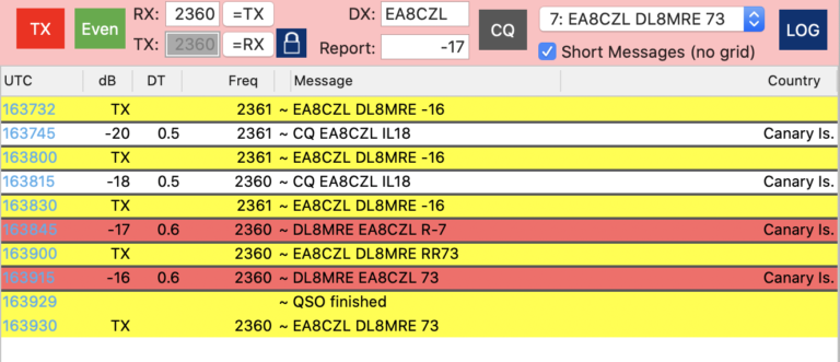
The list in this window contains all your sent messages in yellow and marked with “TX” instead of a dB value.
In addition, it contains all messages that have been received on your RX frequency or messages that are containing your callsign.
This way, you can better focus on your QSO partner and will also see if somebody else is transmitting on the same frequency so you can interrupt your QSO or transmission.
9.8.1. TX
If you hit the TX button, transmission will start at the next odd- or even- time slot. If active, the button has a blue background, if you are currently transmitting, the button is red, otherwise it is gray, indicating a listen only mode.
9.8.2. Odd/Even
FT8/FT4 messages can either be sent at an even- or odd time slot. The other station is receiving and transmitting at the opposite time slot. This button indicates your transmission time slot. You can hit the button to change from even to odd or vice versa. If you are not in CQ mode and answering somebody from the receiving list by tapping (or double tapping) on an entry from the receiving list, this button will be set automatically (to the opposite of the calling station you tapped). So normally, you will only need this button if you are calling CQ yourself and want to start calling either in the even- or odd time slot. If the frequency is free, it is common to start in the even slot but that’s up to you.
The colors for odd (green) and even (blue) are corresponding with the colors of the UTC time in the lists.
9.8.3. RX: TX: Frequencies
The two entry fields are used to enter your RX and TX frequency in Hz relative to the Slice frequency. The values usually range from 100 to 2900 Hz.
If you click on a line in the receive list, the frequencies will be taken over from the line you have tapped.
Usually, you may want to transmit on the same frequency where your destination is transmitting. However, you can manually enter different values or use the buttons =TX which will use the current TX Frequency as TX Frequency or the =RX button which will do the opposite.
If the blue Lock button shows a closed lock, TX and RX frequencies will always be equal.
Hint
Using the same RX and TX frequency is the regular operating mode when answering calls. Only if the other station can’t hear you, you may want to use a different TX frequency. On the other hand, when calling CQ you should always open the lock to allow different RX and TX frequencies (Split mode) as you would otherwise “steal” somebody’s frequency when he would answer on a different frequency.
You can then either enter another RX or TX frequency manually or more conveniently from the Waterfall. For this, just right click at the frequency where you want to TX and select “Set FT8 TX Frequency.
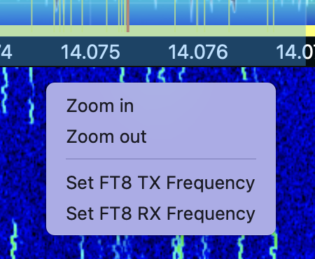
9.8.4. DX
This field is for the Call-sign of the other station and will be pre-filled when tapping on an entry of the receiving list.
9.8.5. Report
This field is the dB report of the other station which will also be pre-filled.
9.8.6. CQ
Using this button, you can switch between CQ mode and answering mode. A blue button indicates the activated CQ mode.
9.8.7. Message selection
Right from the CQ button, you can select a message which will be sent in the next odd or even slot.
If you are in AUTO mode, you usually don’t need to change this message, only if you are in manual mode or want to correct / repeat a previously wrong interpreted or received message.
The “Short Messages (no grid) will no longer start with the message which includes your QTH locator (grid) and instead starts with the report message.
Note
A FT8 message can only get 15 characters long. If the message gets too long maybe because both call signs have extra characters, the QTH locator will be removed automatically.
9.8.8. LOG
Hitting the LOG button will open the logging window with all fields already pre-filled.
This button is not needed if you have enabled “Auto Logging” in the Settings of this FT8 Tool.
9.9. FT8 Settings
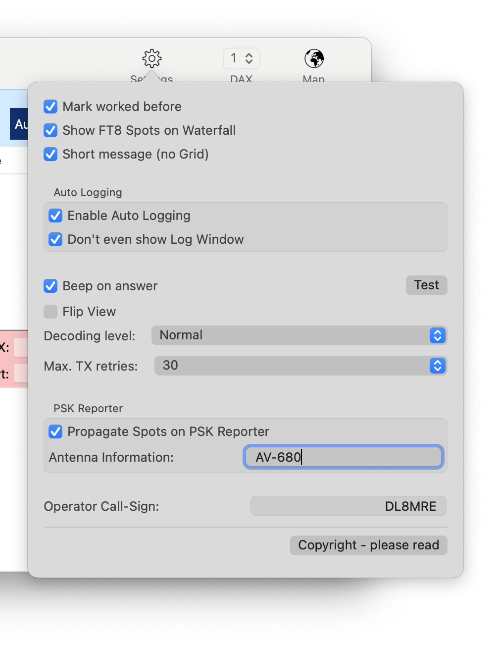
Most of these settings are self-explanatory, or you can experiment with them to see their effects.
When transmitting (TXing), either in response to someone else’s CQ or when calling CQ yourself, the “Max. TX retries” value determines the maximum number of transmission attempts to prevent you from getting stuck in an endless loop.
If you are operating under a different callsign, or using a callsign with a prefix or suffix, simply enter the appropriate information into the “Operator Callsign” field.
9.10. Filter Settings
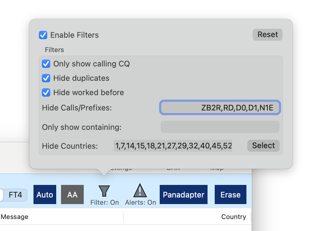
The filter settings help to reduce the number of lines in the receiving list. The filter can be enabled or disabled at the top of this settings screen.
9.11. Using FT8/FT4 for DXpeditions (Fox and Hound)
You can operate as a hound to work DXpeditions (the fox) with this app as follows: First, set the Band selector in the FT8 Tool to Manual and activate Split mode in FT8 by clicking the lock icon to unlock TX = RX. This configuration allows you to monitor the DXpedition’s frequency, typically announced on their website, outside the standard FT8 or FT4 band range. Subsequently, transmit on the frequency where the DXpedition expects to receive your signal. Please note that if the DXpedition responds to your call with a multi-answer message, the app may not automatically log this response. In such cases, you’ll need to manually press the LOG button to log the QSO.
External Software
UDP Log submission
If you want to use another Logging software on your Mac or even your Windows PC, you can use a feature of this App which submits all new log entries to other software via UDP.
This feature can be enabled under Settings and the External Software tab. If enabled, whenever you are adding a new Log entry, this log entry will be submitted simultaneously to the other Logging program. In addition, there is a “UDP Broadcast” button on the Log detail screen which can be used to submit any older or amended log entry as well.
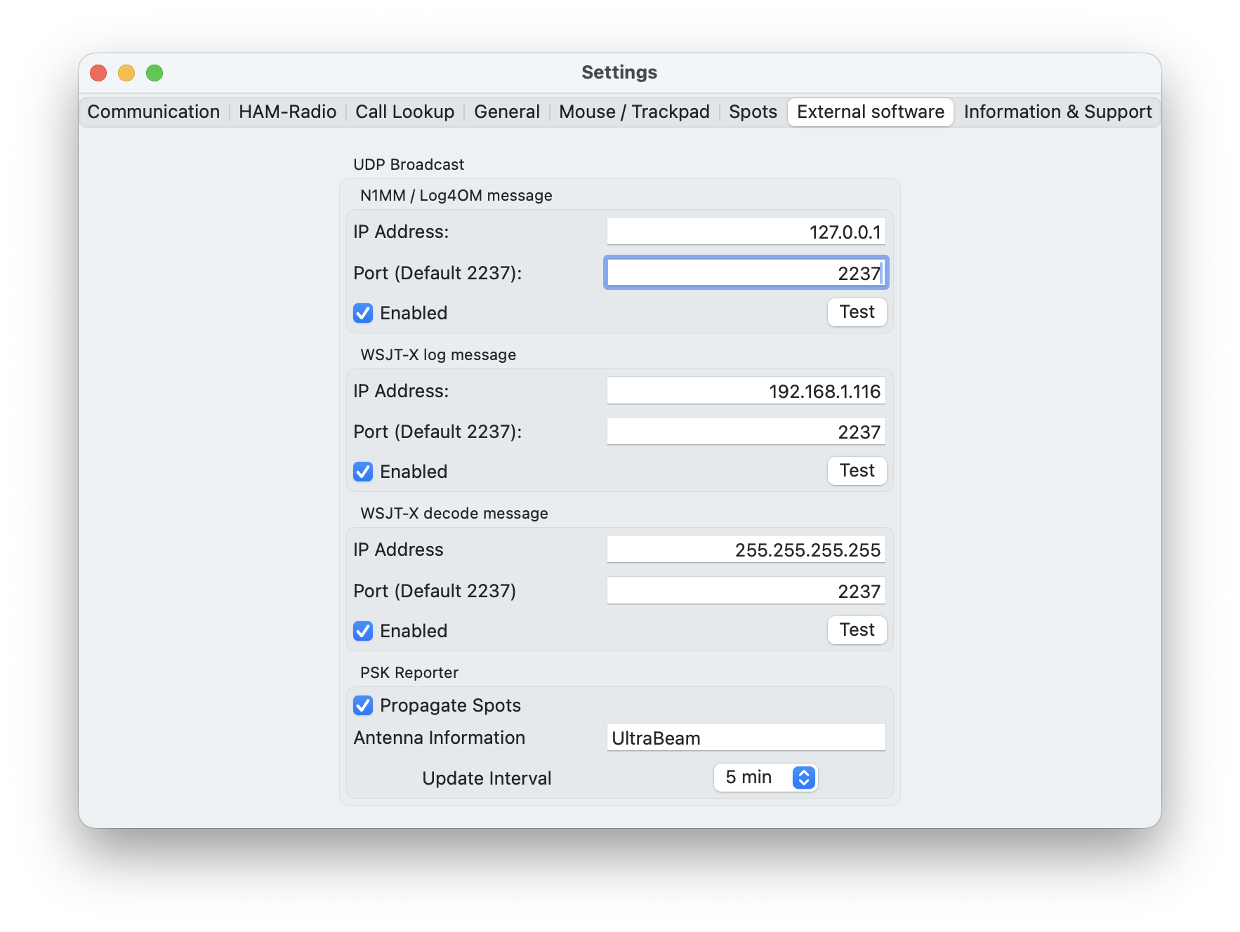
If enabled, whenever you are adding a new Log entry, this log entry will be submitted simultaneously to the other Logging program. In addition, there is a “UDP Broadcast” button on the Log detail screen which can be used to submit any older or amended log entry as well.
For UDP Log transmission, you need to enter the IP Address of the PC/Mac where your other Logging program is running and the required UDP Port. If the program is running on the same Mac, just enter 127.0.0.1 as IP Address. You can also enter the broadcast IP Address 255.255.255.255 but not every software supports this so in doubt, just enter the IP Address of the destination device.
Unfortunately, there are different standards for submitting log entries via UDP. This App supports two different standards:
1.) For N1MM or Log4OM format
This standard is understood by N1MM or Log4OM and others, mainly PC based logging programs.
2.) WSJT-X format
This standard is used by WSJT-X. Every logging software that can receive WSJT-X UDP logging information can be used.
3.) WSJT-X decode message
This standard is used by WSJT-X for FT8 messages which is being used by other external software like grid tracker.
The ports that need to be used for each standard depends on the Logging program. Some will let you enter an individual port number, some have a fixed port number. In any case, the port number used by the logging software needs to be identical to the port entered here.
When clicking the Test button, a sample log entry will be submitted so you can verify if the log entry will be received in your logging program.
From here, you can also enable Spot propagation to PSK Reporter.
CAT Server
Besides using the integrated FT8/FT4, RTTY and HF-Fax tools, it is also possible to use other external software.
In the past, CAT Cables were and are still being used with legacy hardware Radios. It will be used to exchange information like the current frequency between a Radio and a Software or to control the Mode and even the PTT.
This app can emulate such a CAT cable as network interface which means that CAT commands are to be transmitted over the network. That also means that the other Application to send or receive CAT commands can either be on the same Mac or even another PC or Mac.
To maintain these virtual CAT interfaces, open the Radio → CAT Server menu.
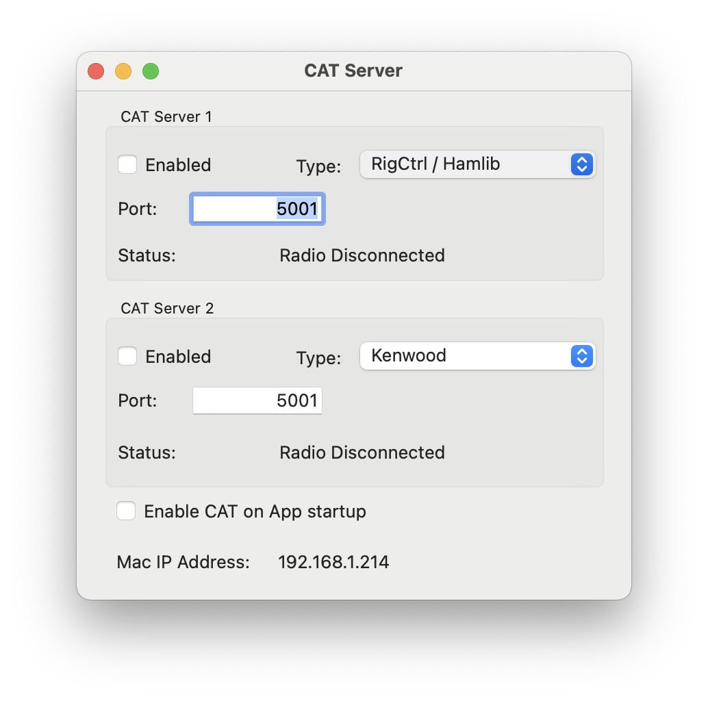
The App supports the following three CAT “Languages”:
Icom CAT
Kenwood TS-2000 and
RigCtrl / Hamlib.
It depends on the other Application, which of these “Languages” you have to choose. You may need to experiment and try different settings and see which one works best.
You can use up to two virtual CAT Cable interfaces at the same time.
For each interface you need to enter a Port. The value you have to enter here depends on the other Software which sometimes allows also to enter a Port number manually or it may use a certain fixed and predefined port number. That port number needs to be identical to the port number to be entered here.
The other Software will also require you to enter an IP Address for the destination. If the Software is running on the same Mac, you can enter 127.0.0.1 which always stands for the local device regardless which individual IP address your Mac would have. Alternatively, and for Software running on other devices, you will need to enter the IP Address of your Mac. For your convenience, this IP Address is displayed at the bottom of the CAT Cable settings screen.
Once you enabled one of the two interfaces you will either see a red warning next to the “Status:” line telling you that a certain setting is wrong or missing otherwise you will see “Waiting”.
Now you can start your external software to establish the CAT connection to this App. In case it was successful, you should see “Connected” here.
Audio Streaming
Whereas the CAT interface is used to exchange radio information and settings between an application and a radio, it is also necessary to route audio between the app and other software.
The Audio Streaming feature of this app now integrates the Common-Radio™ Audio Driver, which provides seamless, low-latency audio exchange with external apps.
To maintain the Audio Streaming settings, open the Radio → Audio Streaming menu.
Note
A third-party audio driver is no longer necessary. However, the option to use one remains available. If you prefer to use loopback audio drivers, you can simply divert audio by selecting the loopback devices in the app audio settings. But please note, this will cause additional latency.
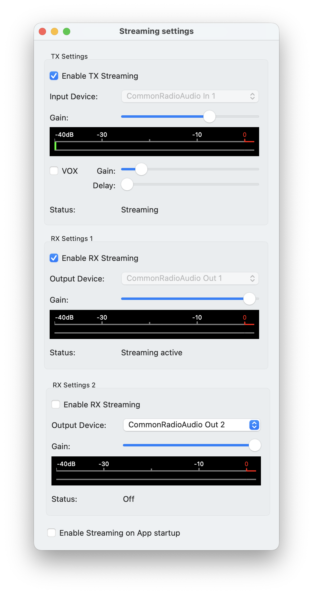
Input (TX)
For audio exchange using Audio-Streaming and the Common-Radio™ Audio interface with an external app, select one of the four available Input Devices CommonRadioAudio In 1 to 4. Once Enable TX Streaming is activated, the app will expect audio from the selected audio device, which should also be set as the Output, Speaker, or Playback device in your external software.
If audio is incoming, it will be visible on the displayed meter, and you can adjust the gain as needed.
Output (RX)
Under RX Settings, you can select up to two devices for receiving. Choose from one of the four output devices CommonRadioAudio Out 1 to 4.
Once RX Streaming is enabled, select the same CommonRadioAudio Out device as the Input, Mic, or Capture device in the external app.
For Radios supporting two concurrent audio channels per VFO both VFOs can be streamed individually. In this case RX Settings 1 refers to the first VFO and VFO RX Settings 2 to the second VFO.
Keying (PTT)
The optimal way to trigger PTT from your external software is to use CAT commands. However, if some programs do not support this, you can utilize the integrated VOX option.
External Software Configuration Examples
WSJT-X
CAT-Server Settings:
WSJT-X CAT Settings:
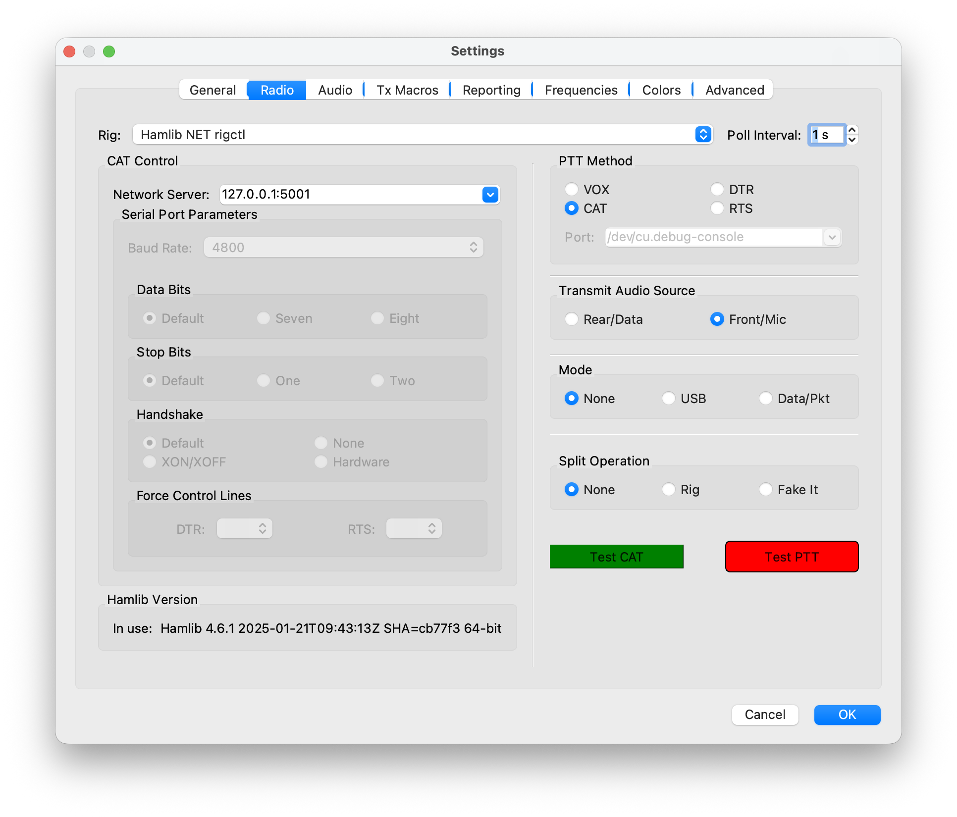
Streaming Settings:
WSJT-X Audio Settings:
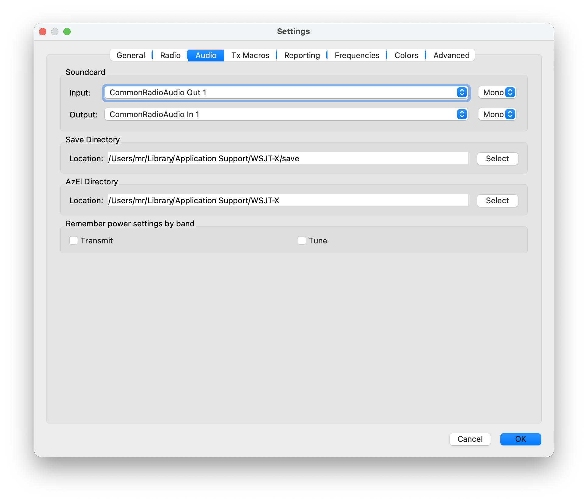
FLDIGI
CAT-Server Settings:
Fldigi CAT Settings:
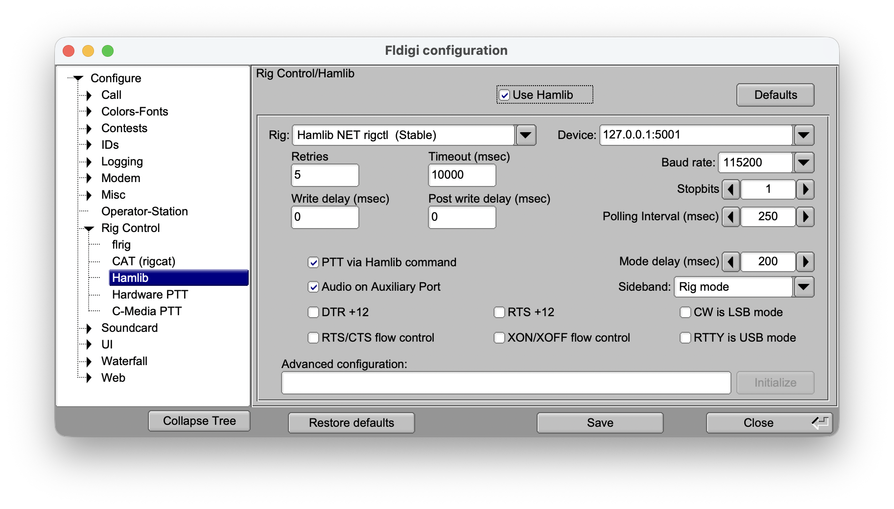
Streaming Settings:
Fldigi Audio Settings:
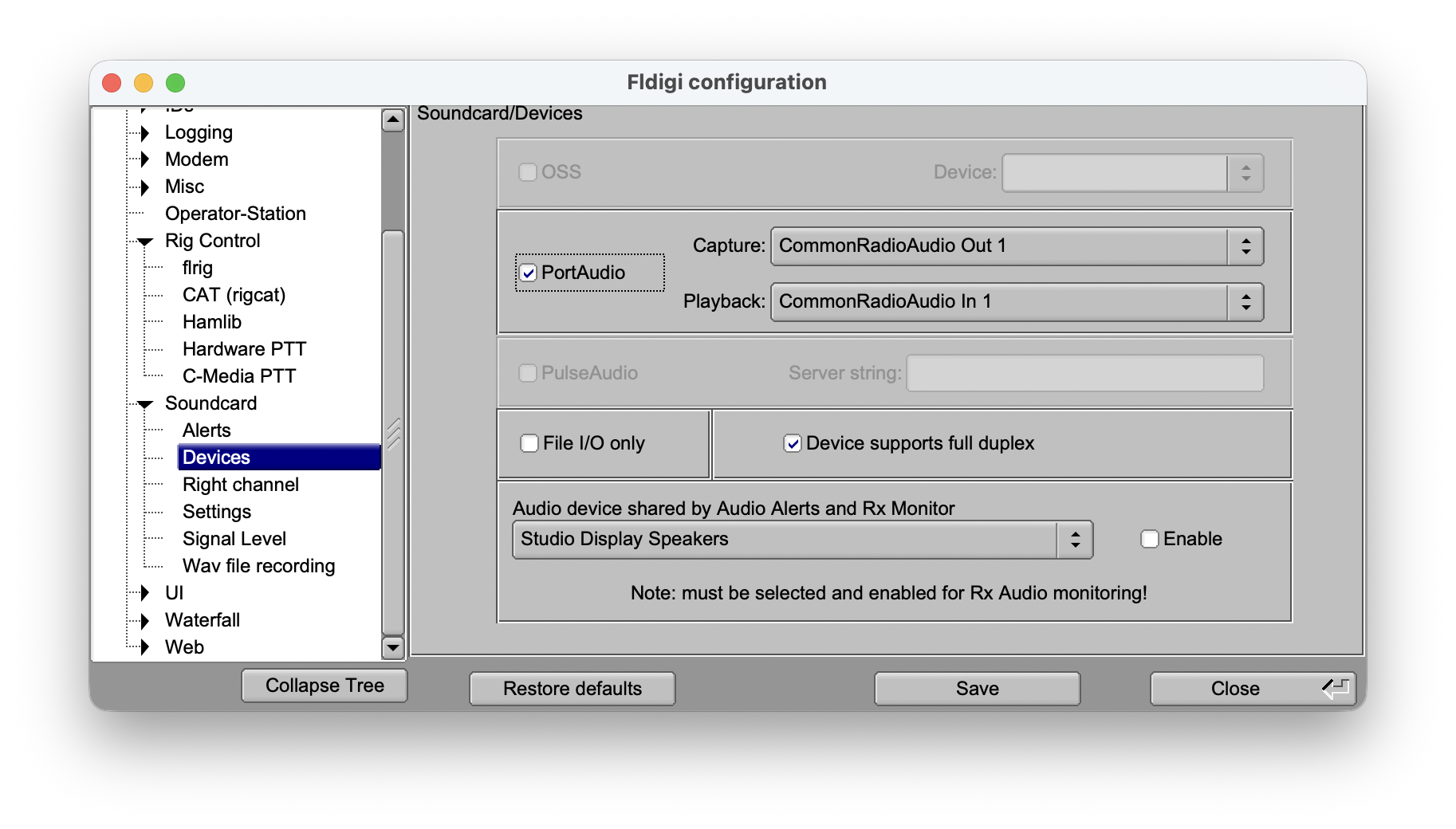
GRIDTRACKER 2
UDP Submission: (under Settings and External-Software)
Gridtracker Settings:
Other Software
The configuration of other external software can generally follow the procedures outlined in the previous examples. If you are using a specific software integrated with this app, I would appreciate receiving your screenshots and a detailed description (if necessary). This will allow to include your setup in this manual, thereby assisting other users.
1. Setting up an IC-705
It is possible to use your IC-705 in “Station mode” or “Access Point mode”. Both modes are explained in the two next chapters individually.
1.1. Setting up an IC-705 in Station Mode
“Station mode” means that your IC-705 will connect to your local WiFi Network. This is the preferred mode when using your IC-705 at home and this is also necessary for remote access over the Internet.
To setup your IC-705 in Station mode, proceed as follows:
Use the Menu key (Menu > Set > WLAN SET) to check or change the following Settings:
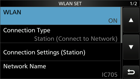
Ensure WLAN is ON and Connection type is Station
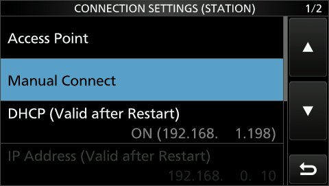
Tap on Access Point to select your own local WiFi network and enter the WiFi credentials to connect.
Ensure DHCP is ON
You may need to restart the Radio at this point if you made changes here. Then revisit this menu.
Once connected you will see an IP Address under DHCP. Take down this IP Address.
Note
This is your Radio IP Address which needs to be used for the Radio setup in the App.
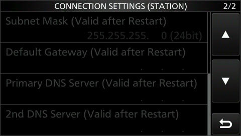
All other settings below DHCP should be grayed out.
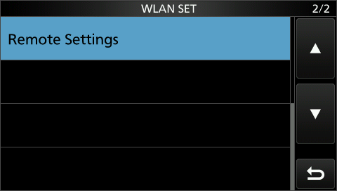
Use the Back button to go Back to WLAN SET
Select Remote Settings
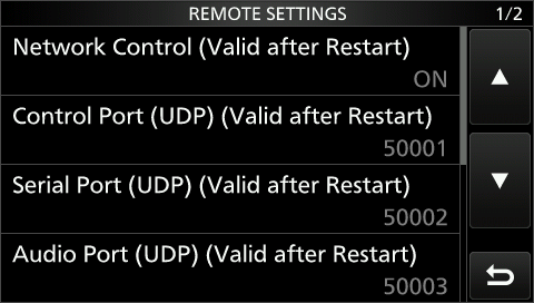
Ensure Network Control is ON.
Verify if the Control Port has a value of 50001.
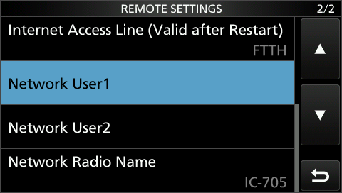
Ensure that Internet Access Line is FTTH
Tap on Network User1.
Now enter a Username and a Password of your choice.
Setting up of your IC-705 is now complete. Now proceed with adding a new Radio to the App based on the information you have collected (The IP Address) or entered (Username and Password) here.
Note
Please keep in mind that you need to restart your Radio if you have changed some settings which are marked (Valid after Restart)
1.2. Setting up an IC-705 in Access Point (AP) Mode
The “Access Point mode” doesn’t require a local WiFi network because the IC-705 creates one on it’s own. You can use this mode for Field Days or whenever you are not at home. However, this mode only allows the App to Connect to your IC-705.
To setup your IC-705 in Access Point mode, proceed as follows:
Use the Menu key (Menu > Set > WLAN SET) to check or change the following Settings:
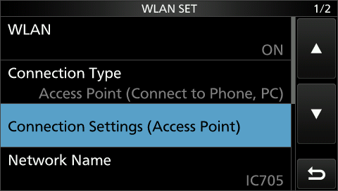
Changing the Connection Type to Access Point
Tap on Connection Settings.
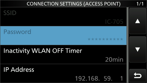
You have to setup a SSID (the WiFi Name) and a Password for your WiFi connection of the IC-705
Note
This is a new WiFi network, don’t enter the WiFi name and password of your current local WiFi network here.
You may need to restart the Radio at this point if you made changes here, then revisit this menu.
Take down the IP Address.
Note
This is your Radio IP Address which needs to be used for the Radio setup in the App.
Ensure Network Control is ON.
Verify if the Control Port has a value of 50001.
Ensure that Internet Access Line is FTTH
Tap on Network User1.
Now enter a Username and a Password of your choice.
Setting up of your IC-705 in AP Mode is now complete.
Now you have to connect your Apple device to this newly created WiFi Access Point of your IC-705.
After you are now connected to your Radio WiFi Access Point, you can proceed with adding a new Radio to the App based on the information you have collected (The IP Address) or entered (Username and Password) here.
Warning
Don’t change the CI-V Address of the Radio. This won’t work.
2. Setting up an IC-9700
Use the Menu key (Menu > Set > Network) to check or change the following Settings:
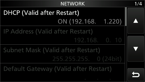
Ensure DHCP is ON and take this IP Address down. All other settings below DHCP should be grayed out.
Note
This is your Radio IP Address which needs to be used for the Radio setup in the App.
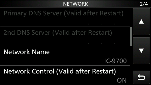
Ensure Network Control is ON.
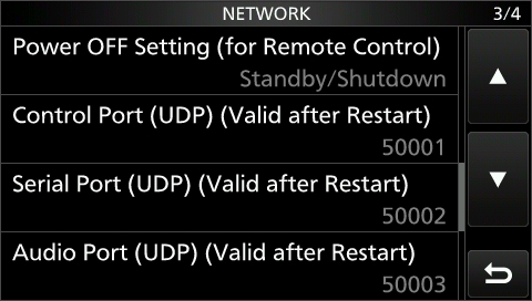
Verify if the Control Port has a value of 50001.
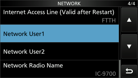
Ensure that Internet Access Line is FTTH.
Tap on Network User1.
Now enter a Username and a Password of your choice.
Setting up of your IC-9700 is now complete. Now proceed with adding a new Radio to the App based on the information you have collected (The IP Address) or entered (Username and Password) here.
Note
Please keep in mind that you need to restart your Radio if you have changed some settings which are marked (Valid after Restart)
Warning
Don’t change the CI-V Address of the Radio. This won’t work.
3. Setting up an IC-7610
Use the Menu key (Menu > Set > Network) to check or change the following Settings:
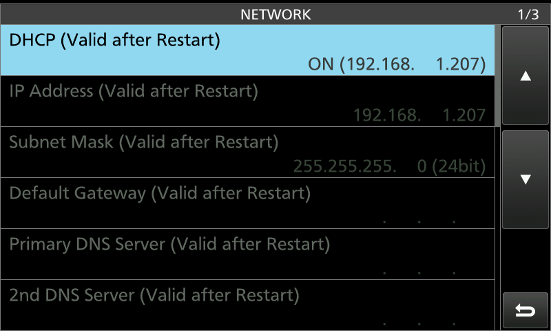
Ensure DHCP is ON and take this IP Address down.
All other settings below DHCP should be grayed out.
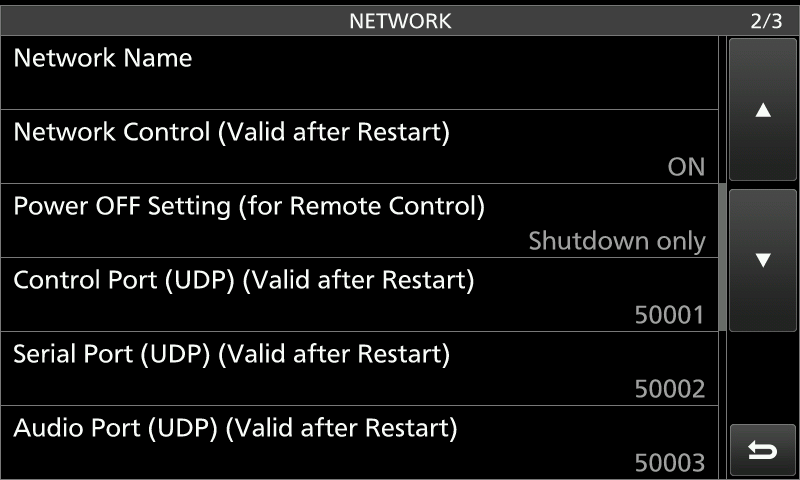
Ensure Network Control is ON.
Verify if the Control Port has a value of 50001.
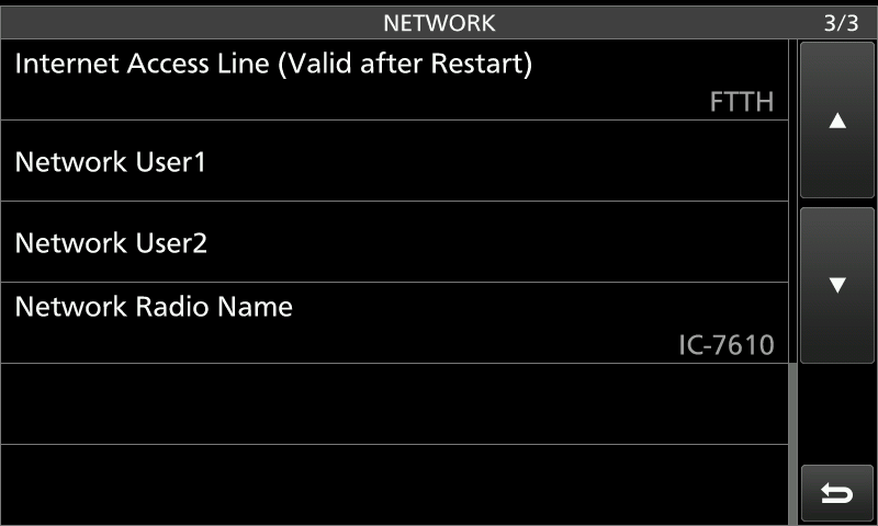
Ensure that Internet Access Line is FTTH.
Tap on Network User1.
Now enter a Username and a Password of your choice.
Setting up of your IC-7610 is now complete. Now proceed with adding a new Radio to the App based on the information you have collected (The IP Address) or entered (Username and Password) here.
Note
Please keep in mind that you need to restart your Radio if you have changed some settings which are marked (Valid after Restart)
Warning
Don’t change the CI-V Address of the Radio. This won’t work.
4. Setting up an IC-7760
The following assumes that you have your IC-7760 Front panel (Controller) and RF Deck working.
Use the Menu key (Menu > Set > Network > Remote Settings) to check or change the following Settings:
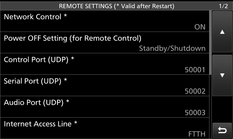
On Page 1/2:
Ensure Network Control is ON.
Verify if the Control Port has a value of 50001.
Scroll down to page 2/2.
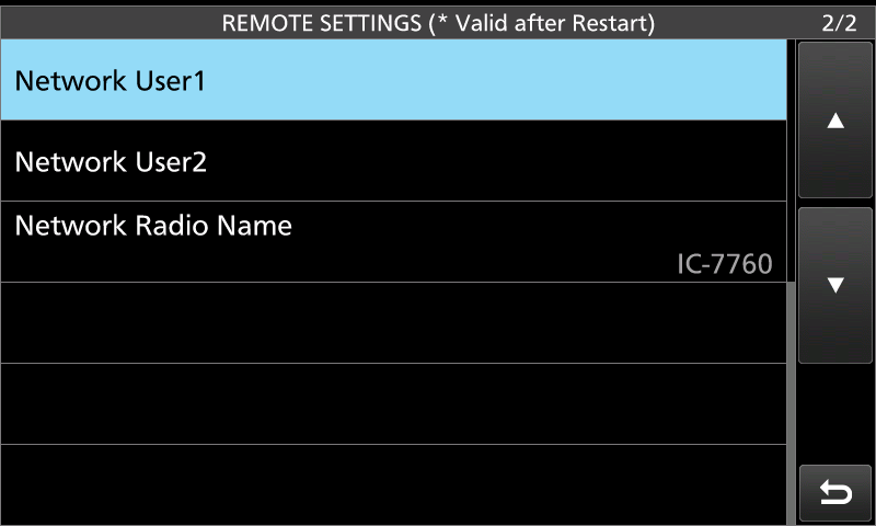
Tap on Network User1.
And enter a Username and a Password of your choice.
Now you need to find out the correct IP Address. The IC-7760 has three IP Addresses, one for the HF-Deck, one for the Controller and one Icom calls LAN. What you need is the LAN IP Address.
One way to find this IP Address is to look up the IP Address in your network router. For this, you will need the so called MAC Address.
The MAC Address for the LAN pf the IC-7760 can be found using Menu > Set > Others > Information.
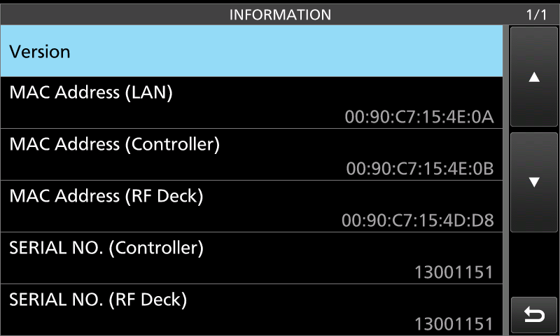
In this example, the MAC Address for LAN is 00:90:c7:15:4E:0A. You can now visit your Routers Configuration Webseite to find the IP Address that relates to this MAC Address.
Setting up of your IC-7760 is now complete. Now proceed with adding a new Radio to the App based on the information you have collected (The IP Address) or entered (Username and Password) here.
Note
Please keep in mind that you need to restart your Radio if you have changed some settings which are marked (Valid after Restart)
Warning
Don’t change the CI-V Address of the Radio. This won’t work.
5. Setting up an IC-7300mk2
Use the Menu key (Menu > Set > Network) to check or change the following Settings:
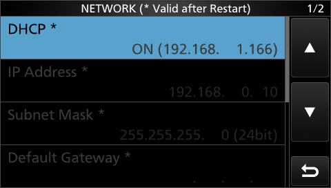
Ensure DHCP is ON and take this IP Address down.
All other settings below DHCP should be grayed out.
Scroll down and tap on Remote Settings.
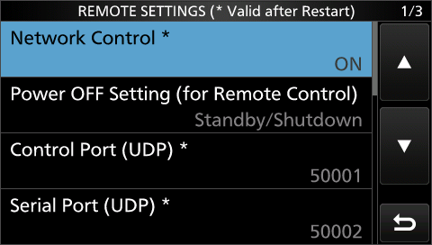
Ensure Network Control is ON.
Verify if the Control Port has a value of 50001.
Scroll down.
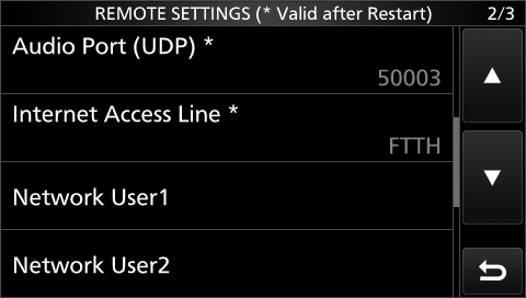
Ensure that Internet Access Line is FTTH.
Tap on Network User1.
Now enter a Username and a Password of your choice.
Setting up of your IC-7300mk2 is now complete. Now proceed with adding a new Radio to the App based on the information you have collected (The IP Address) or entered (Username and Password) here.
Note
Please keep in mind that you need to restart your Radio if you have changed some settings which are marked (Valid after Restart)
Warning
Don’t change the CI-V Address of the Radio. This won’t work.
6. Setting up an IC-7300
The IC-7300 only supports USB an no network connection. As mentioned in the first chapter, the disadvantage is that such a USB connection is very slow and the waterfall will only be displayed at a low speed. Also, it is not possible to connect to this Radio remotely over the Internet.
Use the Menu key (Menu > Set > Connectors) to check or change the following Settings:
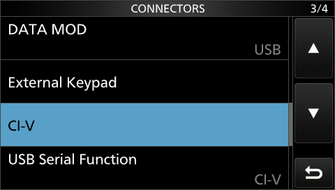
Here, the USB Serial Function needs to be set to CI-V.
Next, tap on CI-V
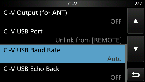
Ensure that the CI-V USB Baud Rate is set to Auto.
Setting up of your IC-7300 is now complete. Now proceed with adding a new Radio to the App.
Warning
Don’t change the CI-V Address of the Radio. This won’t work.
7. Setting up an IC-R8600
Use the Menu key (Menu > Set > Network) to check or change the following Settings:
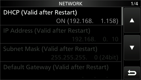
Ensure DHCP is ON and take this IP Address down. All other settings below DHCP should be grayed out.
Note
This is your Radio IP Address which needs to be used for the Radio setup in the App.
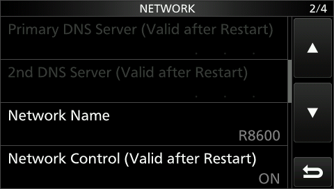
Ensure Network Control is ON.
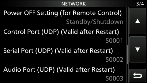
Verify if the Control Port has a value of 50001.
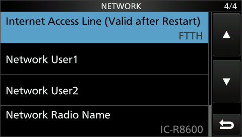
Ensure that Internet Access Line is FTTH.
Tap on Network User1.
Now enter a Username and a Password of your choice.
Setting up of your IC-R8600 is now complete. Now proceed with adding a new Radio to the App based on the information you have collected (The IP Address) or entered (Username and Password) here.
Note
Please keep in mind that you need to restart your Radio if you have changed some settings which are marked (Valid after Restart)
8. Network considerations
Because this App relies on the IP Address of the Radio for connecting to it, it is important to know that IP Addresses may change.
One possibility for a non-changing IP Address would be to manually assign an IP Address to the Radio and not using DHCP.
However, this is not recommended as you may experience problems if you don’t carefully chose the IP Address that don’t conflict with other Addresses on your network.
A better solution is to keep the DHCP (the default) setting of your Radio but instruct your Router instead, to always keep the same IP Address for this device. Unfortunately, there are different terms used for this feature in different Routers. It may be called static-lease or even static-IP so you may want to look into your Router’s manual to find this feature.
Another consideration is to use a secure password. This is especially important if you enable Remote Access as described in the next chapter.
9. Remote access
With this App, it is possible to connect to your Icom Transceiver from outside your home network. For this, you need to let three ports pass your Router to the internet or in other words you need to open three ports in your Router.
Unfortunately, this task will be different from Router to Router so it can only be explained in general here.
The ports in question are the three ports found in your Radio settings under “Control Port (UDP)”, which usually is 50001, “Serial Port (UDP)”, which usually is 50002 and “Audio Port (UDP)” which usually is 50003.
Now you need to access your Router’s configuration website and look for a possibility to open ports in your Router.
Here, you need to open these three ports (50001,50002,50003) to the IP Address of your Icom Transceiver. If your Router want’s to know for which Protocol these ports should be opened, it it only necessary to open these ports for the UDP Protocol. If your Router want’s to know which ports should be used for the inside and which for the outside, you can use the same ports (50001,50002,50003) for the inside and outside. Sometimes you can enter a complete port range like 50001-50003. In some Router you have to open each port individually.
Once this is done, you will already be able to connect your Transceiver from elsewhere but you need to know the IP Address that now needs to be entered when you add your Radio to the App’s Radio chooser.
The IP Address you need is the public IP Address for your network allocated by your Internet Service Provider. You can find out this IP Address in your Router or by visiting one of the whatismyip websites.
However, most likely, this IP Address will change from one day to another. To address this problem, you can use services like https://dyn.com but most likely, your Router also supports additional services. Any of those services will provide you with a unique way to access your Public IP Address which always remains the same. Such an address may look like xxxxx.dyndns.org. Once you have setup everything, you can enter this unique address for setting up your remote Transceiver instead of the IP-Address.
For your convenience, just add another Radio to the “Available Radio” list by using the Add button again. Use a name that differentiates the new entry from your regular local access Radio (e.g. 705 remote), use the aforementioned IP Address and for the other values the same as for your local Radio.
9.1. Testing remote access
For testing, first try to connect to the newly added Radio by still using the home WiFi network. Even though it makes no sense as you could also connect to your Radio directly, it makes sense for testing if Port forwarding and the public IP or dyndns address are both working well. Once you have checked that this is working, try to connect using another network like Cellular or another WiFi.
Important
If you are using an iPhone as Hotspot, you will have to disable “Low Data Mode”, “Private Wi-Fi Address” and “Limit IP Address Tracking” in your Device WiFi settings. This is important, otherwise it will not work.
10. Macro Variables
You can use variables like {CALL} in CW Macros.
These variables will be replaced by values from your settings or log before being sent.
The following Macro Variables are available:
{CALL} |
Will be replaced by the Call-sign currently entered in the Log Window |
{CALLSPELL} |
Will be replaced by the Call-sign currently entered in the Log Window spelled letter by letter |
{SENTRST} |
Will be replaced by the RST Sent value of the Log Window |
{RECRST} |
Will be replaced by the RST Received value of the Log Window |
{NR} |
Will be replaced with the Contest Serial number, maintained in the Settings of the Logbook |
{COMMENT} |
Will be replaced by the Comment value of the Log Window |
{MYCALL} |
Will be replaced by your own Call-sign, maintained in the App Settings |
{TXFREQ} |
Will be replaced by current TX Frequency |
{RXFREQ} |
Will be replaced by current RX Frequency |
{FREQ} |
Same as {RXFREQ} |
{TXBAND} |
Will be replaced by current TX Band |
{RXBAND} |
Will be replaced by current RX Band |
{DATE} |
Will be replaced by the Date entered in the Log Window |
{TIME} |
Will be replaced by the current Time entered in the Log Window |
{ENTER} |
Will send a new-line character |
\n |
Same as {ENTER} |
{NOW} |
Will be replaced by the current time in UTC |
{GRID} |
Will be replaced by your Grid locator, maintained in the App Settings |
{LOG} |
Will cause the current QSO to be logged |
11. D-STAR
For radios such as the IC-705 or IC-9700, the app fully supports D-STAR.
There are only a few considerations. One limitation is that Icom does not support the ability to access, select, or maintain the D-STAR repeater list remotely. This list is only accessible on the radio itself or can be updated via an SD card.
Additionally, the Call/DR button cannot be triggered remotely.
However, it is easy to overcome this limitation. You can simply store your preferred D-STAR repeaters or frequencies in regular memory channels. To do this, select a D-STAR repeater from the internal D-STAR repeater list, switch to DV mode, adjust all settings for your repeater, and then save the current VFO frequency to a desired memory channel. This can be done either at the radio or from within the app.
In the macOS app, you can even edit the memory settings using the Memories Tool under the Radio menu.
Here, you can also check or edit the D-STAR settings for URCALL, RPT1, and RPT2, which will be automatically applied when you select that memory from inside the app.
12. Rotator Integration
Whenever you have a rotator active, such as the Green Heron RT-21, the MetroPWR RT1, or the 4O3A Rotator Genius, you can control your antenna’s orientation from various sections of the app.
One option is the Call-Lookup tool.
When you use this tool to look up a call, the app calculates the azimuth to that call based on your current location. After the calculation, you will see two buttons labeled for the Short Path (SP) and Long Path (LP). Clicking one of these buttons will command the rotator controller to move the antenna to the calculated position.
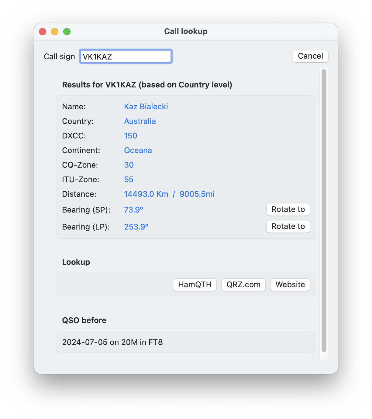
You can access the Call-Lookup tool from different parts of the app, often by right-clicking a call entry, such as in the FT8 list.
Another way to control the rotator is through the maps displayed within various tools. By right-clicking a call on the map, you will see a “rotate to” button.
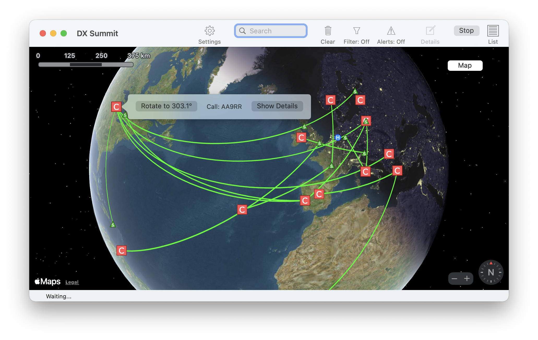
13. USB Serial Cable
You can use a USB Serial cable to connect a CW-Paddle to the Mac. The same cable can also be used to connect a foot switch for PTT activation.
The necessary cable is called
FTDI USB to Serial Cable DB9M (UT232R-200)
It might be possible to use other USB Serial cables but this has not been tested. So if in doubt and if you have to purchase a USB cable anyways, better look for a FTDI cable as mentioned above.
Once your cable is connected to your Mac, you will be able to select this Cable from the Tools → CW Keyer menu.
13.1. Wiring
The FTDI USB Serial cable uses a DB9 male plug.
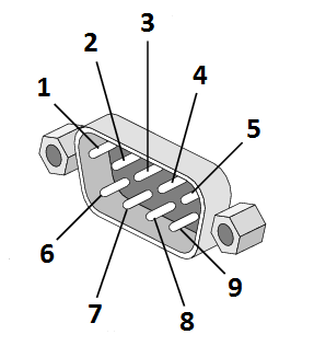
13.2. Connecting a Paddle:
The common (ground) cable of the paddle needs to be connected to pin 7 which is the RTS pin.
The left (dit) paddle needs to be connected to pin 8 which is the CTS pin.
The right (dah) paddle needs to be connected to pin 1 which is DCD
Note
For de-bouncing, please add a capacitor of 10nF between pin 5 (GND) and pin 1 and another between pin 5 and pin 8.
13.3. Connecting a foot switch
A foot switch needs to be connected to pin 7 (RTS) and either pin 8 (CTS) or pin 1 (DCD). Both ways will work.
For de-bouncing please add a capacitor of 100nF between pin 5 (GND) and pin 8 or pin 1 (whichever you use for the foot-switch).
14. HaliKey
If you don’t want to wire a cable as previously described, you can opt for the HalyKey from Halibut Electronics .
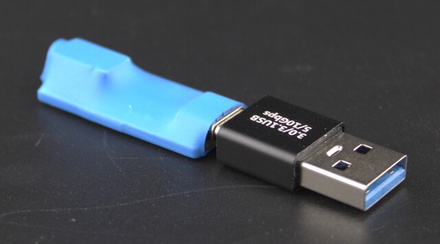
The HaliKey facilitates the direct connection of paddles to a Mac for CW operation. This adapter features a 3.5mm socket on one end and a USB-C connector on the other, incorporating an FTDI serial chip. A USB-C to USB-A adapter is also provided. Installation is straightforward with its plug-and-play capability, and no additional drivers are required. The HaliKey functions similarly to the USB cable outlined in the preceding chapter.
Common Issues
Latest Version
The App is designed to be fully compatible with the latest macOS version and is backward compatible with at least one major macOS version prior. It also runs natively on both Intel and Silicon Macs. If you are experiencing any issues, please ensure that you have the latest version of the App and the most recent macOS update installed.
macOS 26
The app functions smoothly on macOS 26. However, other software may not. For example, most third-party firewalls and virus scanners are incompatible with macOS 26 and must be disabled. You may encounter connection issues, not just with this app, when such software is active. Applications known to cause problems include Norton Antivirus and Little Snitch, but other similar software may also conflict.
Network Error on macOS 26
If you encounter such an error when attempting to connect, try toggling (turn off and then on again) the Local Network access setting (Apple -> System Settings -> Privacy & Security -> Local Network) for the app.
App doesn’t connect to the Radio
If you did follow the instructions on how to setup your Transceiver for the App but the App still can’t connect, this can have various reasons.
The most common reason is, that there was a typo in the settings or the instructions were not followed exactly.
Before you start setting up remote access (which means to connect to your Radio from the internet), you should first ensure that a local connection is working reliable. So in this case, have a local setup first and use the Network Stats tool to see if the error rate is below 0.05%. Once that’s the case, start setting up a remote connection as described under Remote Access. That chapter also explains how to test your Remote access connection.
If you can’t connect, you may see an error message. If the error messages states “error 0”, this means your Radio can not be connected at all. So you might have entered a wrong IP Address or the Radio is not connected to your network. An “error 1” usually means you have entered invalid values for the connection (e.g. a letter or space for the port or invalid address)
Below are a few possible causes of connection issues:
Rejected Local Network access
A common mistake is to mistakenly answer “no” to a macOS prompt asking whether to allow a local network connection. Once this is done, the app can no longer connect to your radio. To resolve this, go to Apple -> System Settings -> Privacy & Security -> Local Network. Then search for the app and ensure that the switch enabling local network access is turned on.
Mac and Radio on different networks
One possibility is, that your Mac and your Transceiver are not on the same network. To prove that, compare the IP Address of your Transceiver (you did already collect in the Transceiver setup steps) and the IP Address of your Mac. You can find this out by opening the Network Stats Tool (Tools → Network Stats). An IP Address consists of four numbers, separated by a . (dot). The Transceiver IP Address and the Mac IP Addresses must both start with the same three numbers. The last number will be different.
So for instance: 192.168.1.4 and 192.168.1.201 would be fine whereas if you have 192.168.1.4 and 192.168.0.10 it would be wrong.
Possible causes are:
Using an old firmware version. Please update your Transceiver always to the latest firmware.
Using a Mesh solution where DHCP is not working correct
Using a so called “guest” WiFi for the Mac and a regular network connection for the Transveiver
Wrong router or Mac settings
Cable issues or something else that prevents the Radio from connecting to your network
Wrong CI-V address of the Radio
Besides the settings mentioned in this manual, the Radio has many additional settings that may prevent the App from connecting. One example is the CI-V address. When this was changed, the App can’t connect. You can revert individual settings back to their default values of your Radio (Menu → Set → Connectors → CI-V → CI-V Address, long-pressing on a CI-V Address and select Default).
Issues with the Radio
In case your Radio has issues, you can try to perform a Partial or Full Reset. A Partial reset can be the first choice as this will not wipe your Settings.
Too old Radio firmware
The App is always tested with the latest firmware released by Icom. In case of problems, just double-check if your Radio is running the latest firmware.
Wrong connection of your local network
For a local connection, you need to have your iPad connected to your Local network via WiFi. Your Radio need to be connected to your local network in the same way (WiFi for the IC-705 or LAN Cable for the other Radios). Only if you want to use your IC-705 without Internet, you need to have a direct connection between your iPad and your Radio (In this case, the IC-705 needs to be setup in AP mode and the iPad needs to connect to the AP of the Radio). In all other cases, both iPad and Radio need to connect to your local network and not to each other.
DHCP not working when using a Mesh
A Mesh network is usually no good idea as it may cause all kind of network issues or delays. Wherever possible use a LAN (cabled) connection or at least a fast direct WiFi connection. Especially on wrong configured Mesh networks you may end up with issues using DHCP because sometimes the DHCP server (usually your Router) can not be reached or even worse you may have two DHCP servers on one network which will not work.
Wifi issues
Wherever you have to use Wifi (e.g. for the IC-705 or the iPad itself) you may experience issues. However, you can always see if issues exist or your measurements to solve the issues were successful by using the Network Stats tool and having a look to the error rate which should be below 0.05%.
If you only have a high error rate when TXing, maybe you “just” have RFi. To prove that, just lower your TX power to 1% and see if that improves the situation
You may also want to look into your WiFi router settings for settings that may improve the reliability. Some routers allow to automatically chose a good WiFi channel. Even though that sounds good, it is not good for reliability if the Router decides to jump to another channel while working with the Radio. So it’s better to see which channel is free and assign that channel manually. But you may need to re-visit that setting from time to time at least once you have problems again.
Another typical issue with WiFi is roaming which not always works well. Sometimes a device might be still connected with the wrong Access point if you are using more than one.
The situation on 5Ghz and 2.4GHz WiFi might also be different. In general, none is better than the other. Both have advantages and disadvantages so it might make sens to disable one or the other to see which one is better for you.
Nothing happens when hitting Connect
If you’re unable to connect when hitting the Connect button, it may be because you have enabled the “Auto connect” setting for a particular Radio, but that Radio is no longer available under the same IP Address. This issue can be resolved by accessing the “Available Radio” list, which may have been skipped if the “Auto connect” setting is enabled.
To regain access to the “Available Radio” list, follow these steps:
Open the App Settings.
Select the Communication tab.
Click on the “Available Radio” button.
Once you have access to the “Available Radio” list, you can review the settings for the Radio and/or unset the “Auto connect” setting. This should enable you to connect to the Radio without any further issues.
App disconnects or quits – Issues with IC-705
Even though this should not happen, it can happen if the network connection is not good. Please read the next point for a solution.
Stuttering Audio or poor Radio responsiveness
As all data to and from the Transceiver will be transferred over the network, it is essential that your network is healthy. While this is easy to achieve with a LAN connection, it may be tricky for the WiFi connection of an IC-705.
To see, if there are any connection issues, use the Network Stats Tool. It should not show an error percentage higher than 0.05 %.
If there is a higher error percentage only for the TX Packets, maybe you have EMC / RFI issues. Try to lower your power and see if this helps.
If you have a higher error rate for an IC-705, most likely you need to move your Icom closer to your WiFi access point or other other way round.
If you are experiencing just temporary audio drops, you can increase the output buffer size in the top (gear Icon) Audio menu.
Another common cause for WiFi issues is bluetooth. Try (at least temporary) to turn off bluetooth on your iPad to see if that makes a difference.
Connection error
If the App would quit unexpectedly or forced-quit, it had no chance to tell the Transceiver that the connection should be closed. The Icom Transceivers may take some time until they got aware of a cut connection. In such a case it may happen that you see an error message when trying to re-connect.
In that case, just wait and try again a bit later. If it still doesn’t work, try to power-cycle your Icom.
In some cases, even if it looks as you did wait long enough and you see the Waterfall, it might have been too early and it can happen that certain data can not be received from the Transceiver. Sometimes, for instance, the Frequency is missing. In that case, disconnect again using the Disconnect button and re-connect.
For connection errors with yout IC-7300 see further down under Issues with an IC-7300
Too high (or low) audio gain / ALC
You may experience a too high or too low audio gain, especially when working in FT8. This gain depends on your particular Transceiver and might be adjusted for best performance. You could either adjust this so called “LAN Mod Level” using the Set Menu on your Radio or more conveniently from inside the App by using the Radio Settings tab. Before adjusting the LAN input gain slider, you can turn on the ALC meter by long-tapping on the Power meter and select ALC. While transmitting (e.g. by calling CQ in the FT8 tool) you can adjust the slider so that it is right before the ALC value doesn’t increase anymore.
After using the App, I can no longer use the Radio, Microphone is not working anymore
There are only a few settings that are changed when the App connects to your Radio in order to let the App use the Radio. One of these settings is the Microphone selection. When using the Mac as Microphone source (by right clicking the Mic button and select either Mic Net or Mic USB) you will have to change that back before disconnecting if you want to continue to use the locally connected Microphone.
However, under the Radio settings (Radio → IC-xxxx Settings) you can instruct the App to revert such settings back to the desired values upon disconnection. Here, you can decide if the App should select back your locally connected Mic.
Mouse or Trackpad behaving wrong
If your Mouse or Trackpad is not working as expected, have a look to the Mouse and Track-pad setting of the App under SDR-Control → Settings and the Mouse / Trackpad tab. Try to disable the Trackpad if you are only using a Mouse or vice-verse. You can also try the Legacy Mouse setting in case you are using a Mouse, not supported by macOS.
If you are using a Logitech Mouse along with the Logitech Software, better disable or uninstall this software as it contains a few bugs. The Mouse will even work without this software – or try the Legacy Mouse setting.
If you are using an Apple MagicMouse, this Mouse can be used as Trackpad.
Some Windows or Menus are cut and not fully visible
The app provides a lot of information and therefore it takes advantage of a good screen resolution. All Macs are offering enough screen resolution for this App but sometimes a lower resolution has been selected. To change this, open the Apple menu → System Settings and select the Displays Icon.
Issues with an IC-7300
macOS no longer needs any driver for connecting an USB device, especially not for the IC-7300. However, you may have installed a driver as it was requited often in the past. As such drivers a no longer necessary, they may even prevent using the USB connection to the IC-7300. An indication for a wrong behaving driver would be, if you can only find the three USB devices of your IC-7300 by different names other than usbserial-…* for the Device connection and the two **USB Audio CODEC… devices. If your devices are named different or you remember that you did install an USB driver in the past and are experiencing connections issues, maybe the drivers are the cause of the problems. So you need to look for a way to completely remove such drivers.
Other connection problems could be caused by using other programs with your IC-7300. These programs may lower the USB Baud Rate if it is set to Auto (the default value) or if they turn of the USB Transceive mode.
If that’s the case, try to connect again after changing the CI-V USB Baud Rate to 115200 , the CI-V Tranceive to On and CI-V USB Echo to Off (note there are similar settings without USB in their name.
A common mistake is to confuse the the virtual Audio Ports (devices) for the IC-7300 with the devices of your Mac. It is important to only have Mac Audio devices selected in the App Audio settings (the Gear Icon) like here:
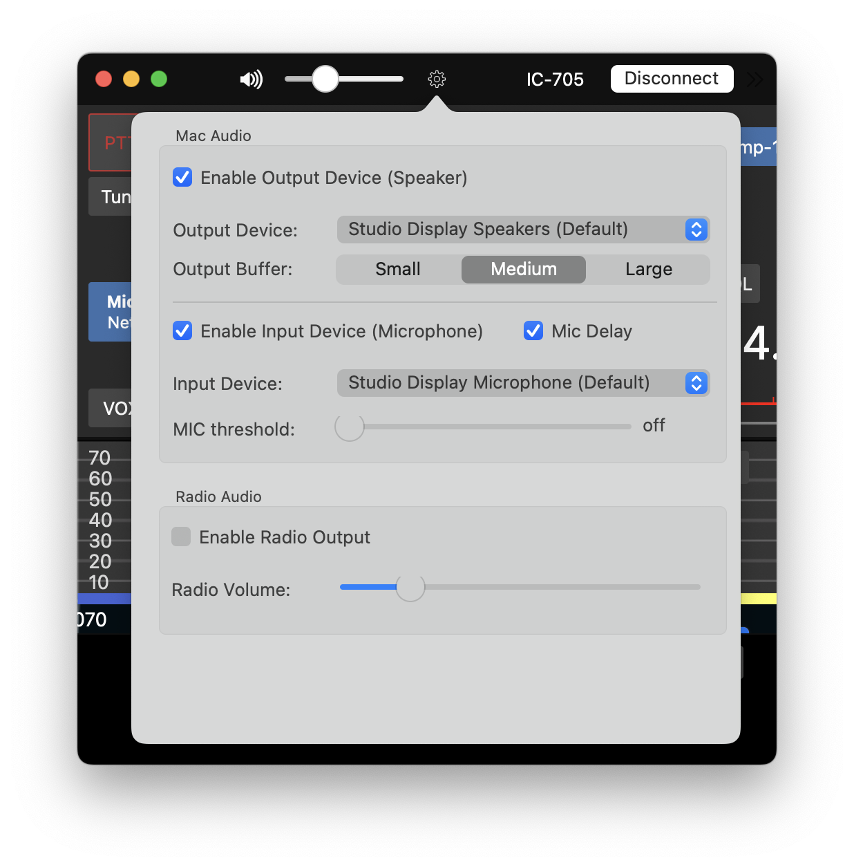
By no means have any USB Audio CODEC selected here.
On the other hand, for the Device (under Available Devices) it is important to select USB Audio CODEC for both, the input and output device as follows:
If you can’t select “USB Audio CODEC” here for input or output, the device is currently in use maybe by another software or by the system itself. Once it is, it can no longer be selected for anything else.
You can double check if you acidentally selected the USB Audio CODEC for your Mac by opening the System Sound Settings. (Apple Icon -> System Settings -> the red Sound Icon).
Here, keep “Output” selected and check if “USB Audio CODEC” is NOT selected. Next select “Input” and check if “USB Audio CODEC” is also NOT selected here.
Once “USB Audio CODEC” is no longer selected here or in any other Software that could potentially use this device, you should be able to select these devices in SDR-Control.
Another common issue when using an IC-7300 are wrong settings for the two USB Audio Codec devices. To check and correct this, open the Apple Audio MIDI Setup app (press Command + Space to open Spotlight and search for “MIDI”).
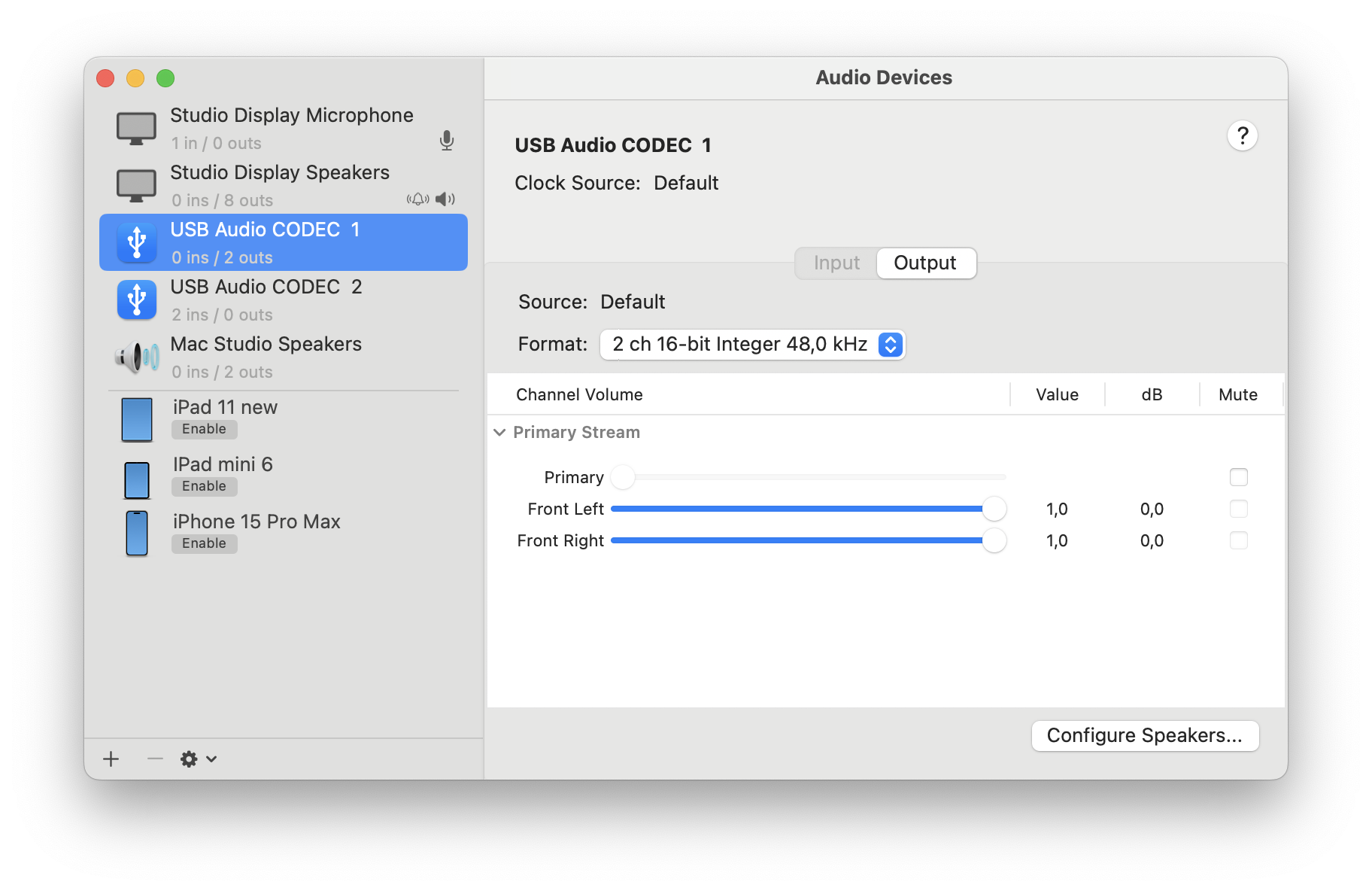
For the Output Device, ensure that the gain sliders (Front Left and Right) are set to the far right (1.0).
For both USB Audio Codec Input and Output Devices, ensure that the Format is set to “2 ch 16-bit Integer 48.0 kHz”.